Let's do the Twist Again
Last revision of this page: March 23, 2025

Actually, the functioning of a floppy cable should be easy to understand, shouldn't it? Yes, but! Here are a few questions that keep coming up:
- Why do most cables have a twist?
- Why are „both“ floppy drives jumpered to the so-called 2nd drive when I have a 1st drive A: and a 2nd drive B:?
- How do I connect a floppy drive to an external DB37 connector?
- How do I crimp a card edge connector to a flat ribbon cable?
- Why are there such exotic cables that have 50 lines?
- What is daisy chaining?
Why do Most Cables Have a Twist?
Why are Floppy Drives Jumpered to the 2nd Drive?
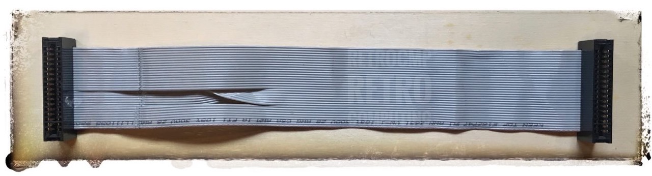
Let's start simple. In figure 1 you see a very simple cable for a single floppy drive. A edge connector is located at both ends. In the left half you can see that several wires have been twisted.
With the right plug you connect the cable to the floppy disk controller, the left side goes to the first and only 5.25" floppy disk drive A.
In figure 2 you see a cable for two floppydrives, which could have come from an IBM PC 5150/5160. A edge connector is located at both ends. In the left half you can see that several cables have been twisted.
The oval graphic is to be ignored for the time being. A further connector is attached here, but I will come to that later.
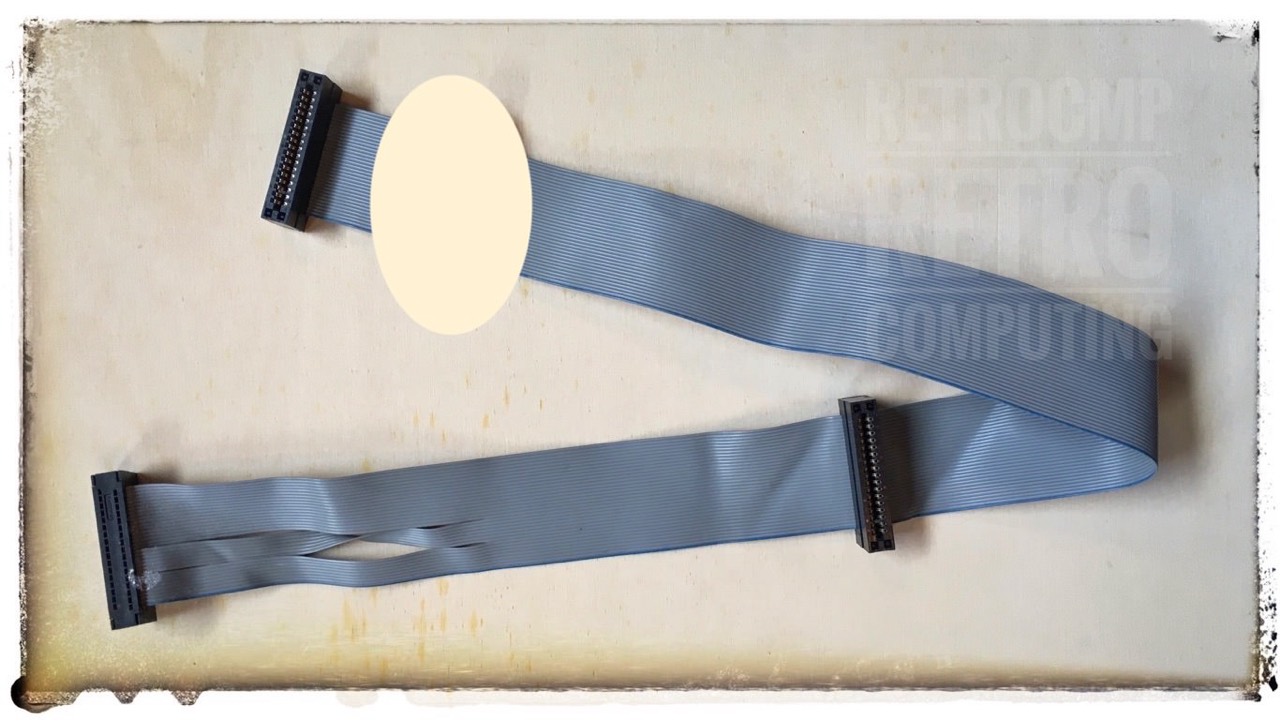
At the top left is the edge connector for the floppy controller and at the bottom left, after the twist, is the edge connector for drive A. The edge connector before the twist goes to drive B.
So what does this twist do? This twist distinguishes between drive A and drive B.
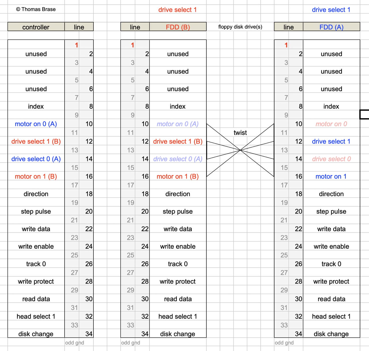
In the pre-PC/DOS era, there were four drives as standard that could be connected - with ONE floppy cable - to a controller. These were selected on the respective drive with the so-called drive select jumper DS. The names are DS0, DS1, DS2 and DS3, but sometimes also DS1, DS2, DS3 and DS4. This type of addressing was also called DAISY-CHAIN.
For the computer specialists of those days, this was everyday business. With the revolution of the PC among the masses, however, this was somewhat complicated.
IBM decided (perhaps rightly) that actually requiring users to select DS0 for drive A und DS1 for drive B was a bit taxing. Was there an easier way? As it turns out, by putting a twist in line 10 to 16, both drives can be DS1, but the one after the twist looks like DS0 to the controller. The twist, then, makes life easier for the PC installer.
(with labelling DS0 to DS1)
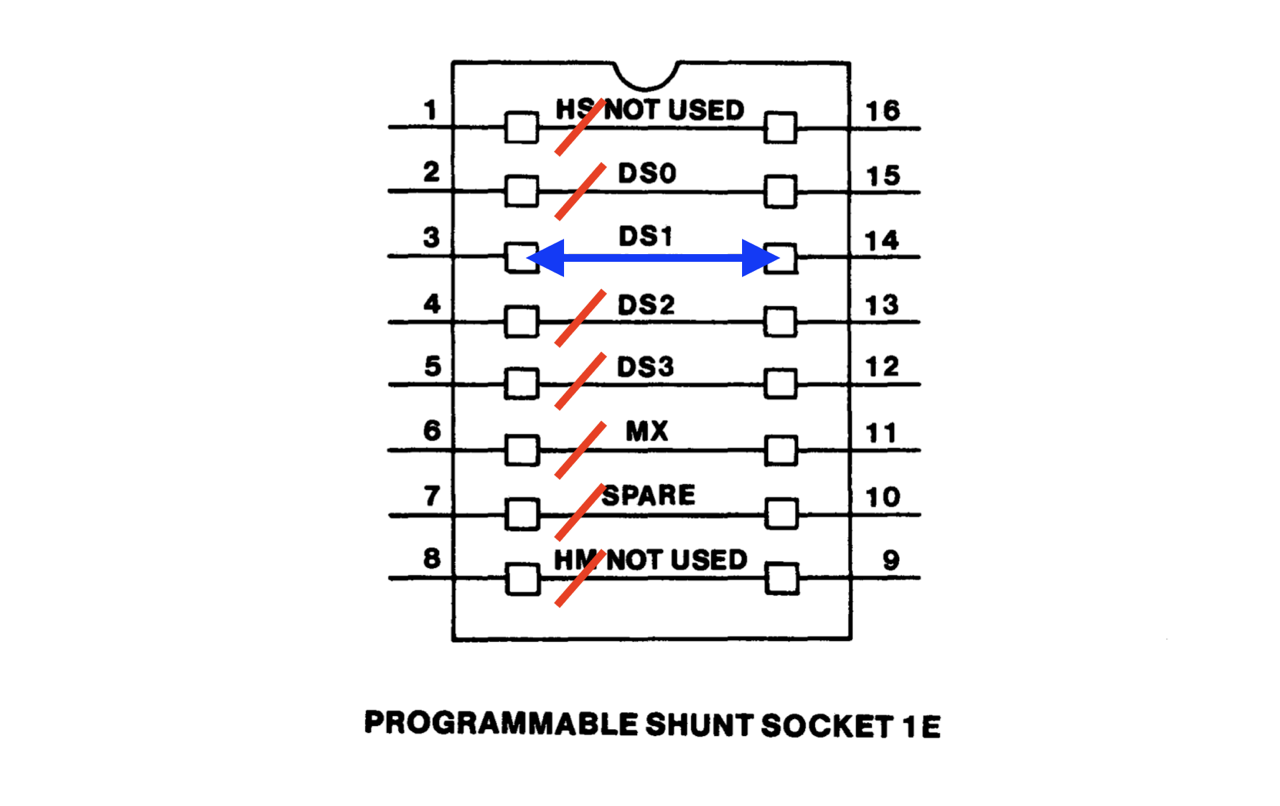
Figure 4 shows the so-called programmable shunt of the Tandon TM100-2 schematically. Here a connection is made between line 3 and 14 at DS1 (drive select 1). In the Tandon TM100-2, this connection is made by a special metal clamp.
The standard PC floppy cable (for two drives) therefore always has this twist and ALL drives are ALWAYS set to the second address (DS1). The drive behind the twist always responds as A and the drive in front of the twist responds as B! You can therefore connect a floppy drive in front or after the twist. It is always correct! [1]

For more information, see [mm91] page 398.
How do I Connect a Floppy Drive to an External DB37 Connector?
Nothing could be simpler! Take a look at figure 6.
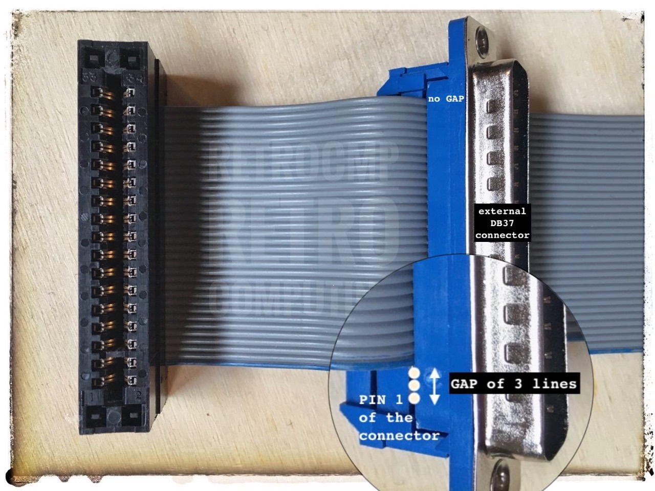
From the cable originally intended for internal use, I made a cable for external use. With this cable, I can easily test another drive on my IBM PC or XT, for example. Two internal and two external drives can be connected to the original IBM floppy controller!
How do I Crimp a Card Edge Connector to a Flat Ribbon Cable?
My very simple method. Works perfectly.
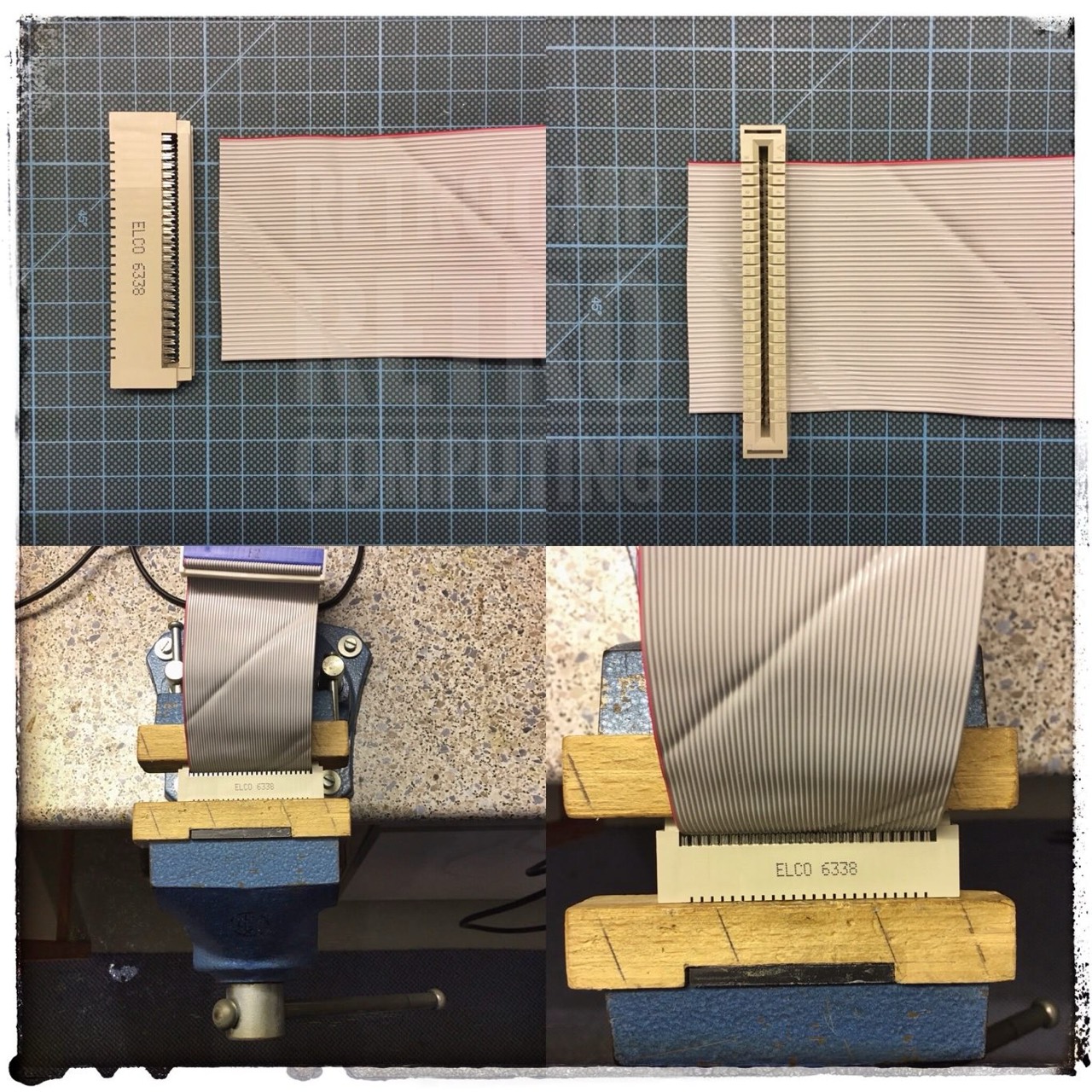
If you want to crimp a twist, it is advisable to fix the three parts of the flat cable with an adhesive strip on both sides, both in front of and behind the plug to be inserted. Then you can press the adapter on as usual between the adhesive areas. Finally, you only have to cut off the overhanging area. If you do not fix the three cable bundles properly, the individual lines will always slip in the edge areas.
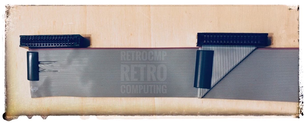
In picture 9 I have fitted a cable (with twist) with two card edge connectors. The whole cable had to be adjusted in length so that the connectors fit exactly after bending. The length between the two connectors is exactly matched to two drives standing next to each other in a double diskette cabinet (RX180). The cable must be bent so that the red line (1) is always on top. It looks more difficult than it is. I need this cable to connect the RX180 to my IBM 5150.
Why are There Such Exotic Cables That Have 50 Lines?
Back in the late 70s and early 80s, the 50-pole flat ribbon cable was by no means exotic. It was the standard cable for the 8 inch floppy drives. It was not until the advent of the 5.25 inch drives that the 34-pin cables were used. There was no longer a need for 50 wires.
What is Daisy Chaining?
Floppy drives are connected by a cabling management called daisy chain. The name is descriptive because the cable is strunk from controller to drive to drive in a single chain. All drives have a drive select (sometimes called DS) jumper that must be set to indicate a certain drive's physical drive number. The point at which the drive is connected on the cable does NOT matter; the DS jumper indicates how the drive should respond. [2]
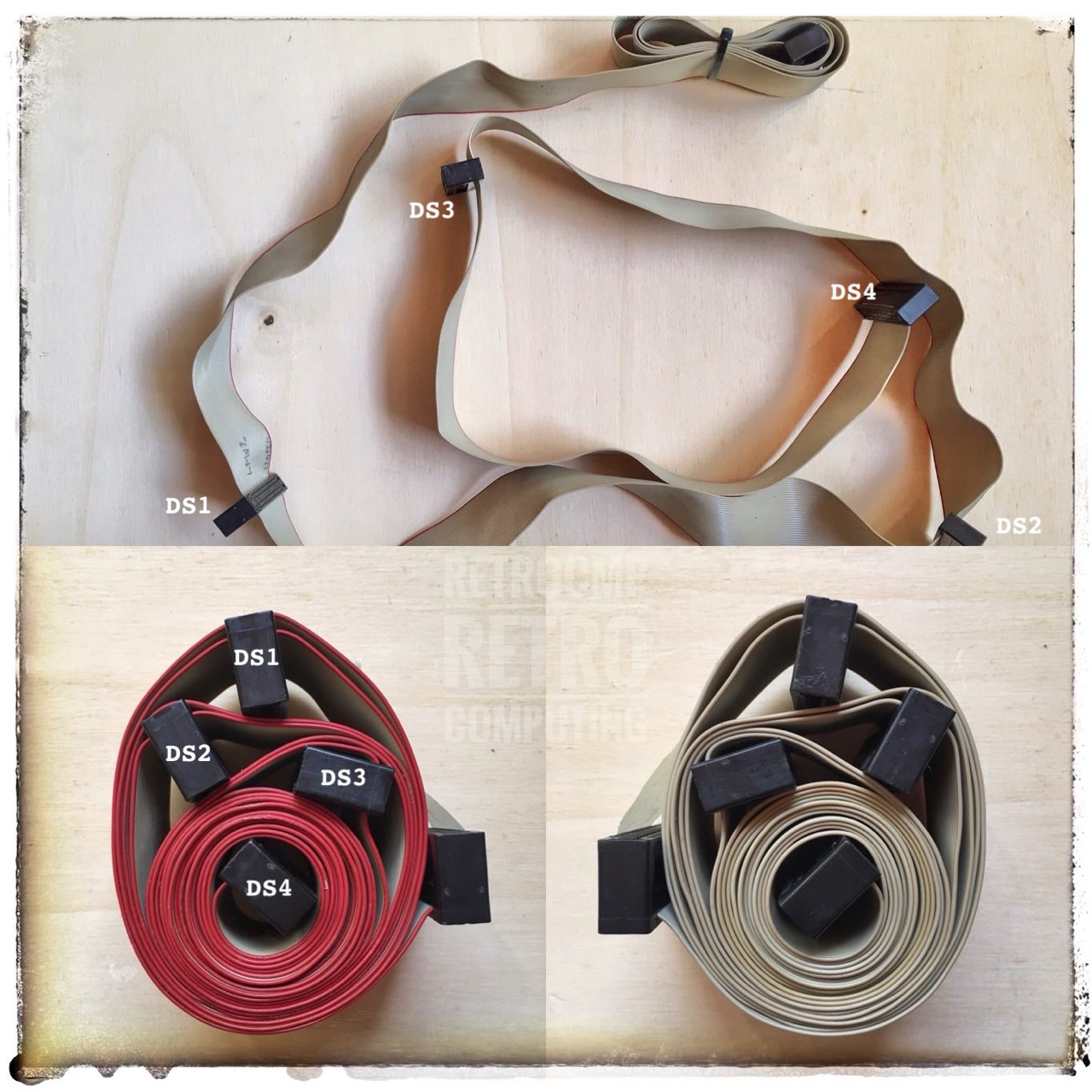
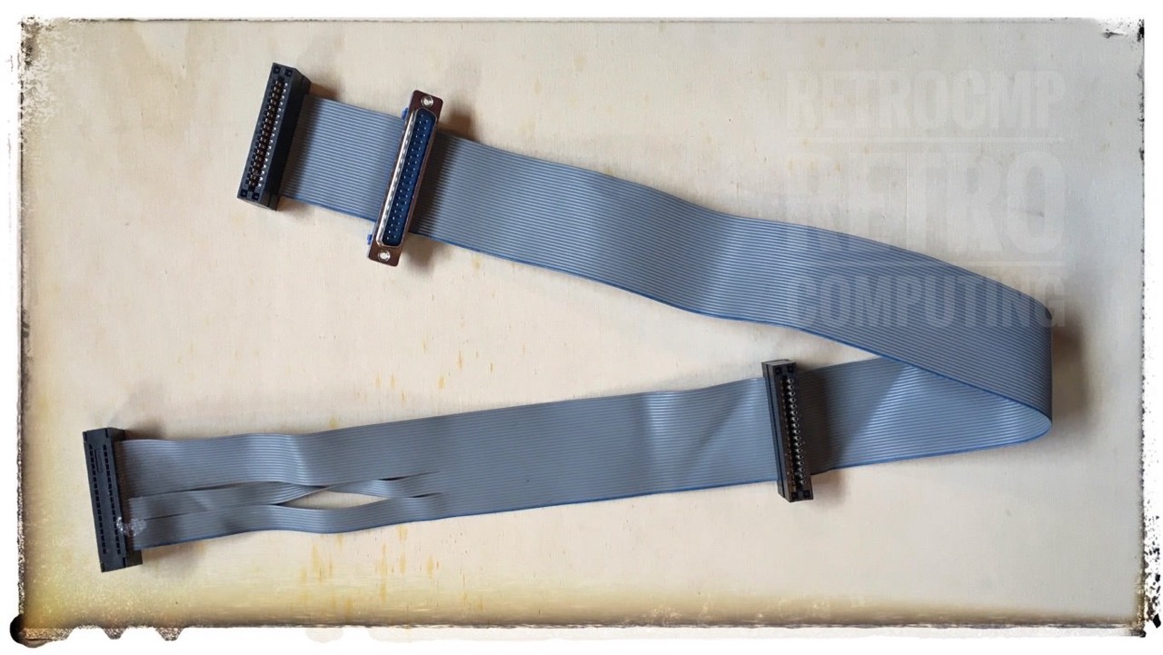
The cable in figure 10 has a length of approx. 2.5 m, i.e. 8.2 feet!
In German: „Kaskadenschaltung oder Verkettung". This daisy chain cable is a different to the later IBM compatible cables (see above). Here, both drives are always jumpered as DS1, whereby the 1st drive (A:) is always at the end of the cable (after the cable twist) and the 2nd drive (B:) is always before the cable twist. Attention, the designation here are DS0 and DS1 (DS2 and DS3 do not exist).
References
- (↑) Literature: [mm91] page 398
- (↑) Literature: [ms92] page 535