Cromemco 8K Bytesaver
- Introduction
- For Your Safety
- Settings
- Tests
- Repairing
- Programming
- Contemporary Witnesses
- Internal Links
- External Links
- Technical Manuals
- Others
- References
Introduction
Don't Waste Time Loading from Tape ... Put a Chunk of EROM into Memory Address Space.
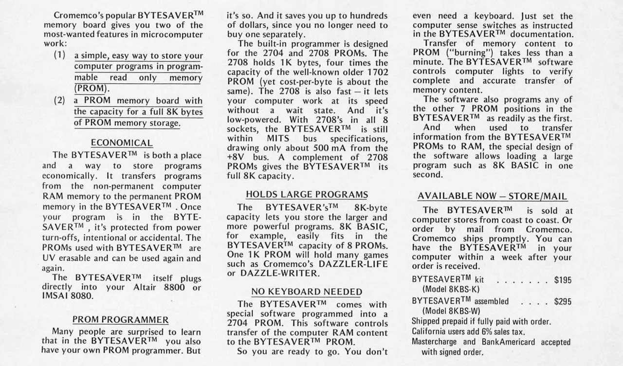
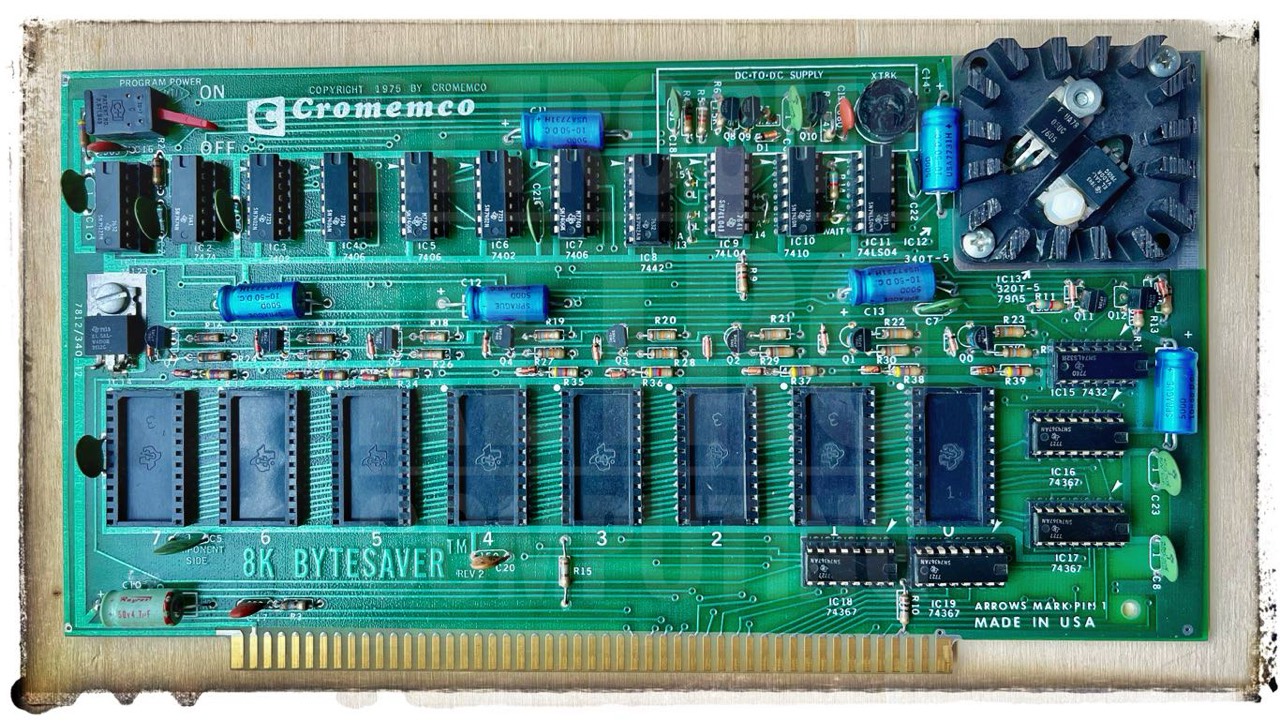
The Cromemco BYTESAVER is a novel and quite useful idea for the person who wants to have his or her software instantly available without wasting the power needed to keep volatile memory alive: This product is a combination EROM memory board and programmer, designed for the Intel 2704 (512 byte) and 2708 (1024 byte) erasable read only memories. It plugs directly into one slot of the Altair 8800 or IMSAI 8080 bus structure, and has a maximum capacity of 8 K bytes if all 8 sockets are loaded with 2708s. [4]
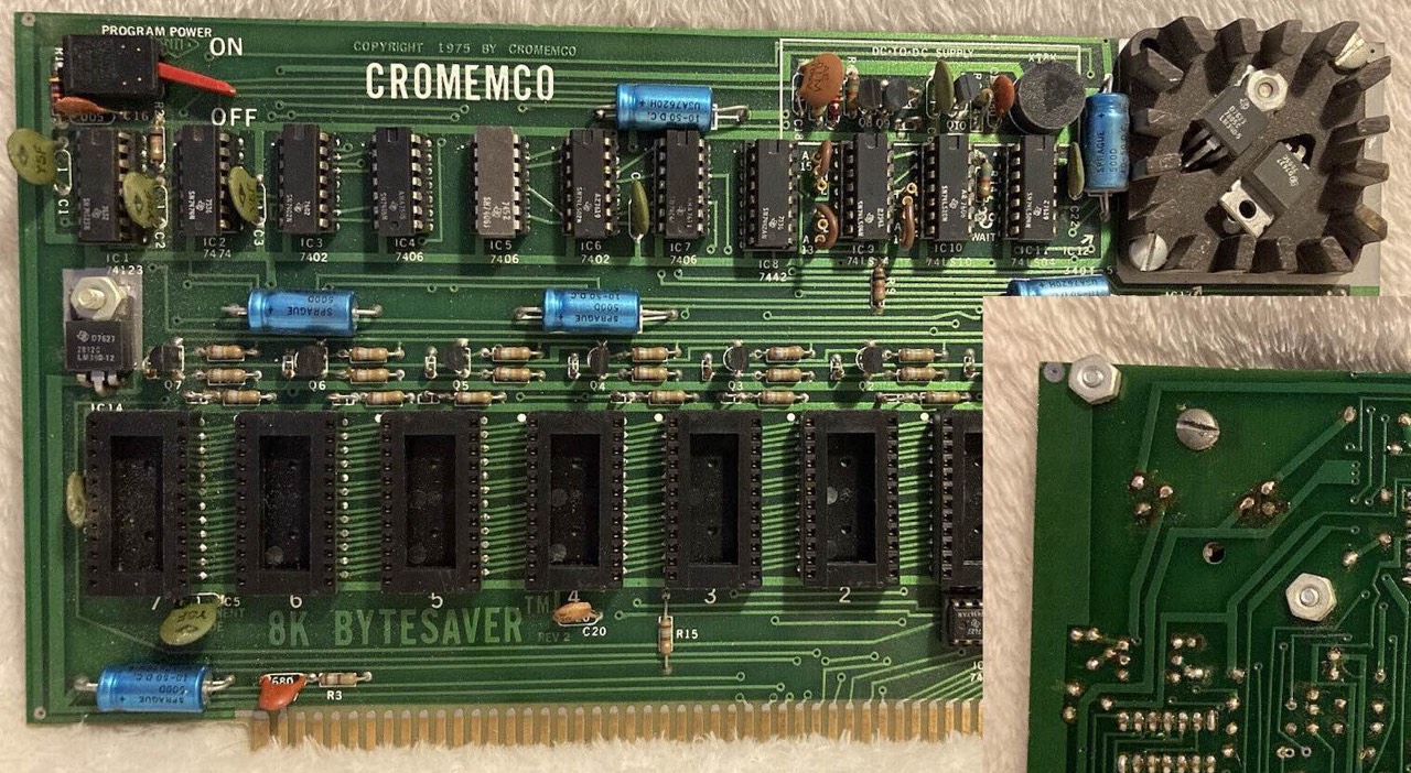
The Cromemco Bytesaver is a read/write, non-volatile memory board, plug compatible with the Standard-100 (S-100) microcomputer bus. The Bytesaver has the capacity for eight 2708 U.V. erasable PROMs for a full 8K bytes of memory.
The Bytesaver contains an integral PROM programmer along with a DC-to-DC supply for generating the programming voltage. Programming is accomplished by a series of memory write operations to the PROM being programmed. [3]
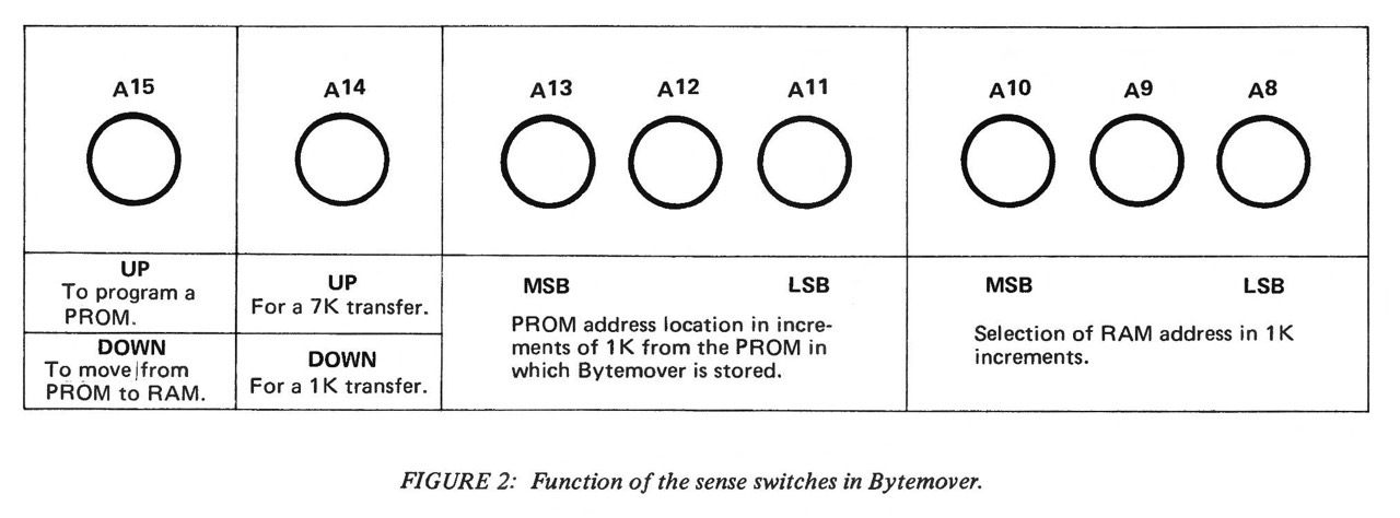
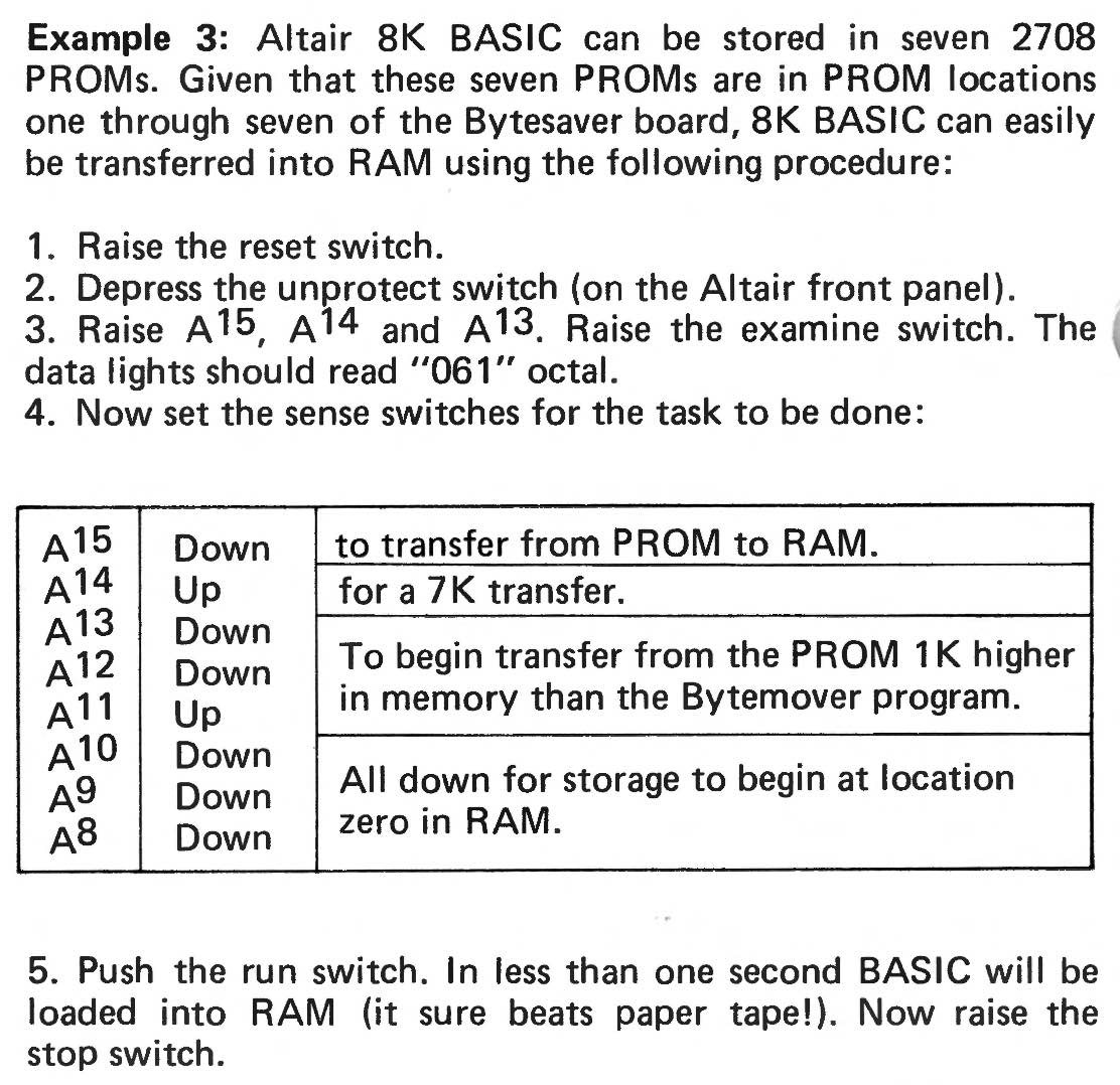
From today's perspective (including mine), it's hard to imagine how it was back then. The basic version of the IMSAI or Altair, for example, consisted of the CPU board, a 4K RAM card and the SIO card for the terminal output. Nothing more. With the help of this PROM card, for example, it was now possible to load the Altair 8K Basic into RAM with a touch of a switch and get started. Exactly this process is described in example 3 of the BYTEMOVER software.
The 2704 which comes with the board contains software [BYTEMOVER] customized for the Altair and IMSAI hardware which uses front panel sense switches to control loading of selected EROM chips from a block of volatile memory. [4]
These examples in particular give a wonderful insight into how these first computers such as Altair or IMSAI worked at the time: "Moving bytes from PROM to RAM".
Logo
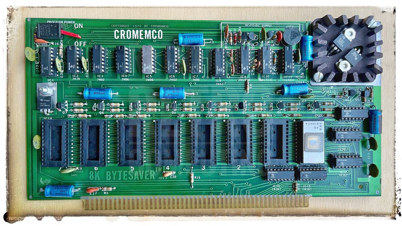
Meanwhile I have two Bytesaver 8K, with and without the Cromemco C logo, both are dated 1975 (when I think about how old I was in 1975).
My Rating
In addition to this card, I also have the comparable one from Solid State Music, the SSM-PB1. In my experience so far, the Cromemcon 8K Bytesaver is more reliable when it comes to providing the programming voltage (25V).
For Your Safety
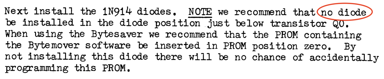
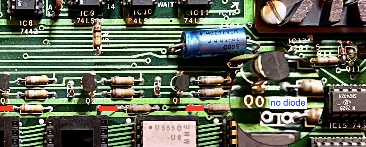
Diode
Program Power Switch
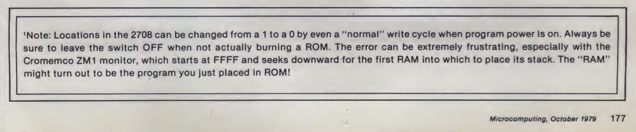
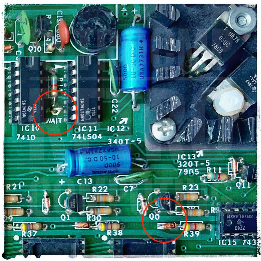
The red switch at the top left - PROGRAM POWER - should always be set to OFF to prevent uncontrolled writing of an EPROM.
Wait State
Should you wish to use low speed 2704s or 2708 (access times greater than 450 ns) in your Bytesaver, be aware there is a provision for a wait state. Simply insert the jumper wire between IC10 and ICll. No jumper need be inserted when using full speed PROMs. Jumper is also required for 4MHz operation. [3]
Settings
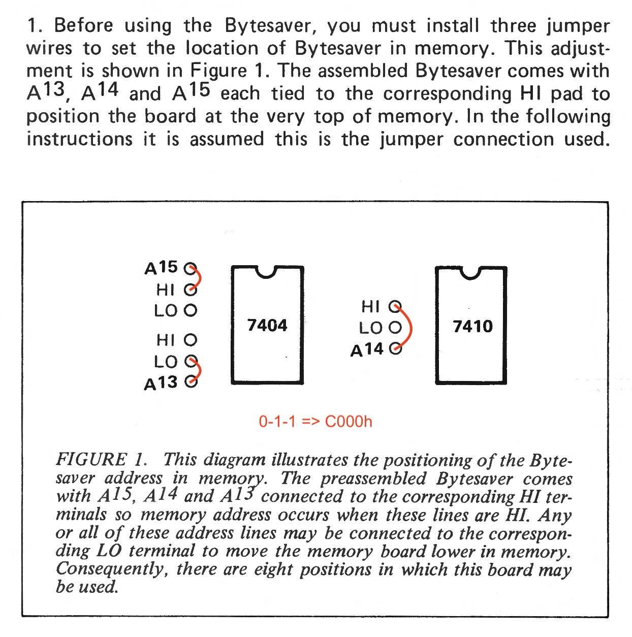
I am currently using the Bytesaver in my N* Horizon with the Vector 4.0C monitor. Therefore the memory areas B and E are a no-go in my case. This leaves only C000-DFFF, since a contiguous 8K area is needed. Thus only a 48K CP/M can be used.
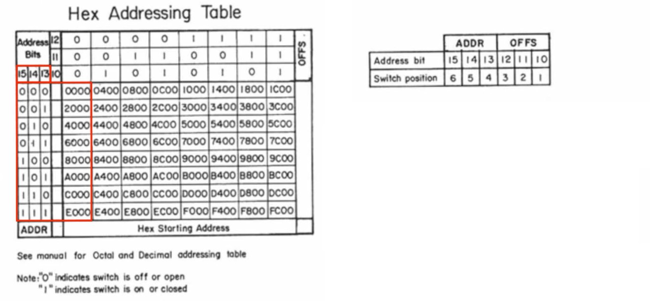
The following are the start addresses for the corresponding EPROM locations. In location 0 you may only be able to read, not write; see above under diode.
- C000 (- C3FF) read only if diode below Q0 is missing
- C400 (- C7FF) r/w
- C800 (- CBFF) r/w
- CC00 (- CFFF) r/w
- D000 (- D3FF) r/w
- D400 (- D7FF) r/w
- D800 (- DBFF) r/w
- DC00 (- DFFF) r/w
With the Cromemco Bytesaver 8K, only the red bordered area is important.
Tests
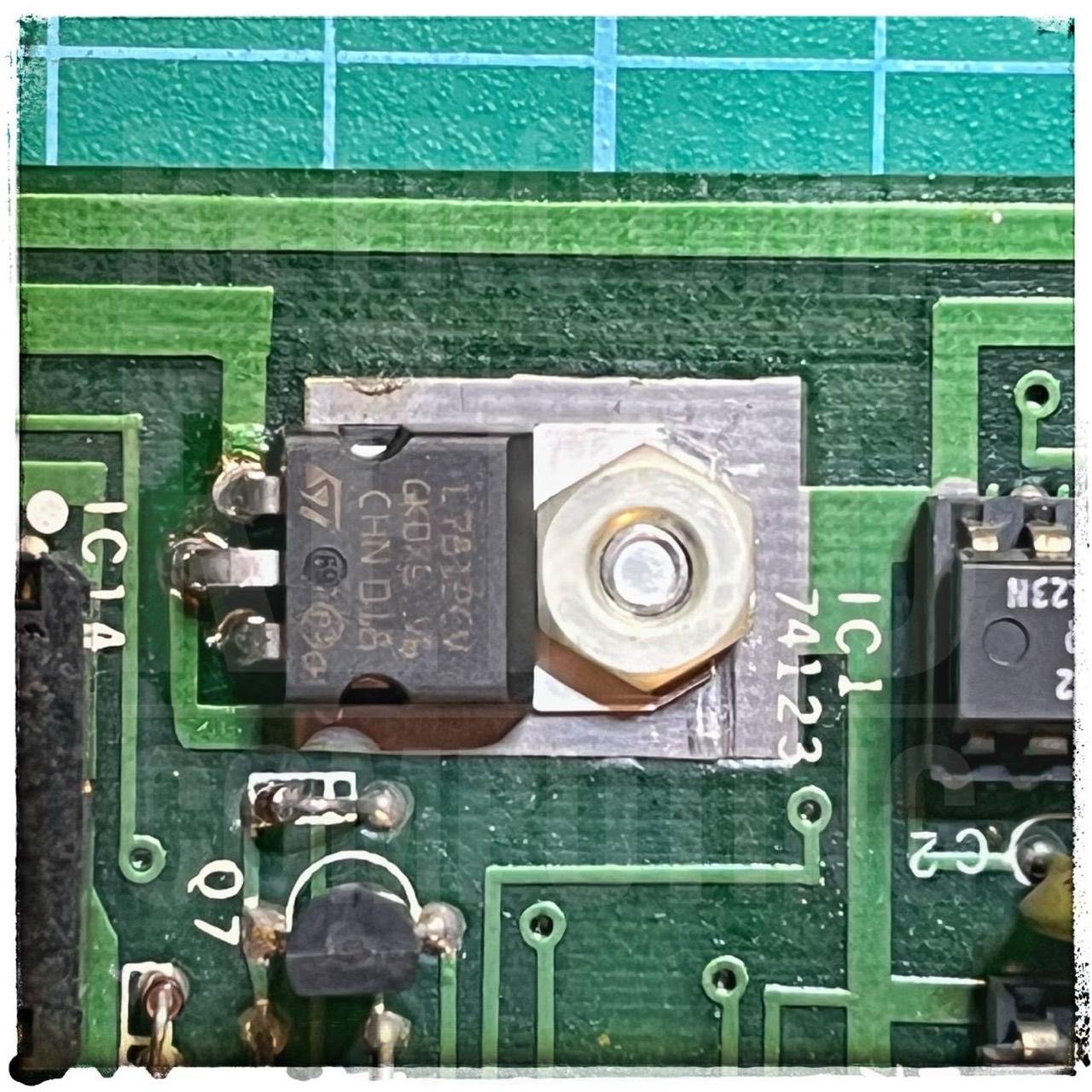
The first test was a complete disaster. Short circuit on the -16V line on my N* Horizon PCB. One inch of the conductor path was blown off. Why? see next. The fixing screw of the 7905 regulator damaged (shorted) the +16V line; and also the -16V line. Read next ...
Stupidity must be punished! And who is the idiot? Me, of course.
First I slept a night and then I analysed the problem again. I was the idiot and fixed the 7905 regulator myself. Why, it can't transfer heat loosely. And that's how I started the avalanche. But now comes the positive. I have really learned a lot.
Circuit Board Check
To avoid this severe mistake, the following check is always recommended in the old S-100 board building instructions. Actually, it is mandatory. And now I know why. As I said, stupidity must be punished!
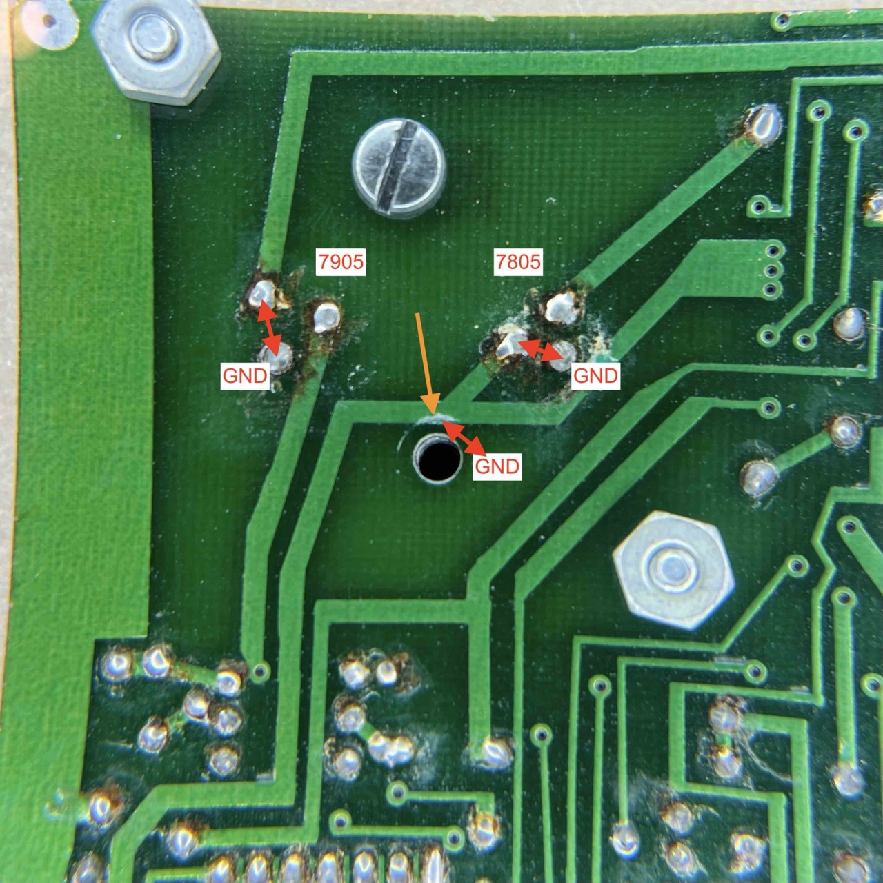
Check every unkown board to ensure that the +8, +16, -16 volt buses are not shorted to one another or to ground (GND). Using an ohmmeter (multimeter), make the following measurements. You should measure no continuity (no beep) in any of these measurements.
Negative voltages (7905) are of course only needed by a few S-100 cards but these are the most dangerous ones.
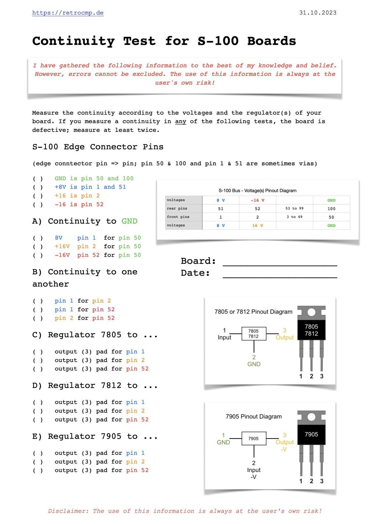
These simple tests take a maximum of five minutes, but can save you several hours of work!
Heat Generation
The heat development of the two voltage regulators is within limits. In my case, I have installed a powerful 12V fan (50x50mm) exactly on the side and slightly below the heat sink. The temperature hasn't exceeded 40 degrees Celsius so far. This fan sucks the air from the card space to the side of the PSU. This area is in turn cooled by a fairly quiet but very powerful fan (150x150mm).
Repairing
My 1st Board
According to Jonathan Chapman I first replaced all three voltage regulators (7805, 7905, 7812; all date codes are from 1976) and then I fixed my selfmade short circuit.
And if you (this is me) can also read now, that's even really better! Long story short: I have done everything wrong here that one can do wrong.
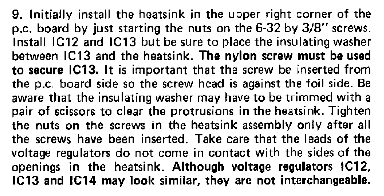
You must use a plastic screw & nut and a thin insulating plastic tape between heatsink and the 7905 regulator. There must be absolutely no contact between the 7905 regulator and the heatsink.
Now that I know about this problem, I have also been able to detect this fact on other S-100 boards with 7905 and 7805 regulators on a same heatsink! This mistake will not happen to me again.
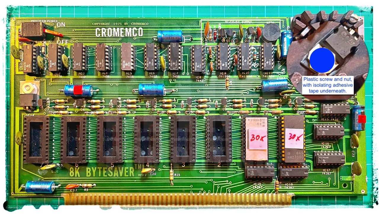
The label 30x on the two EPROMs should mean that I used 30 programming loops. Actually, 50 or 100 loops would be correct.
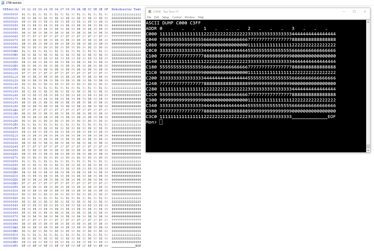
Below is a comparison of my test data with the 2708 EPROMs read out on the N* Horizon at C000h. Success!
More about the actual programming process can be found under EPROM 2708.
My 2nd Board
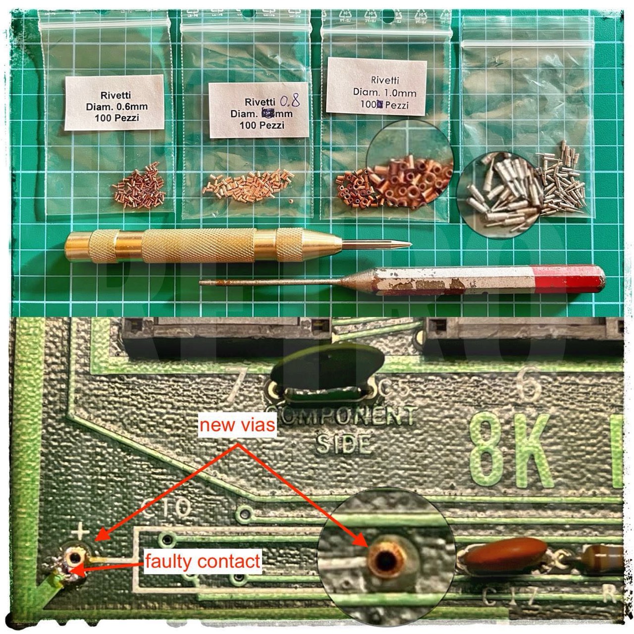
On my second board, everything was fine with the regulators, but I had to replace the pins for the address coding and various faulty vias. I bought the copper inserts in diameters of 0.6 - 0.8 - 1.0 mm in Italy. With the appropriate mandrel and the pin punch, a new via is quickly made; it's very easy. Sometimes you have also to fix a broken contact between via and the conductor path.
Programming
More about the actual programming process can be found under EPROM 2708.
Contemporary Witnesses
Robert Roeder: ... I see the 7805 is also marked LM340-5, the earlier version I believe, and the board was designed by Roger [Melen] at Cromenco at the time I was at Processor Technology. The person who did their boards and I had a discussion once about PCB layout. If you notice many of the traces on the Processor Tech boards are horizontal and vertical, not going at funny angles. They all worked, mine were more aesthetic to the eye. [1]
Internal Links
External Links
- S100 Computers: Cromemco 8K Bytesaver
Technical Manuals
Others
- Roberts, Steven K.: Sweetening the Bytesaver, Kilobaud Microcomputing, Oct 1979, page 176ff
References
- (↑) Robert Roeder, Facebook Group, Vintage S100 Computer Enthusiasts, 2023-10-01
- (↑) Processor Technology, General Purpose Memory Module - GPM, 1977, page 2-5
- (↑) ByteSaver Instruction Manual, 1976, page 1
- (↑) 1976-08_BYTE_00-12 Speech Synthesis, page 50
- (↑) 1976-05_BYTE_00-09_Shooting_Stars, page 3