Solid State Musik IO4
- Introduction
- Settings
- Issues
- Circuit Board Check
- Internal Links
- External Links
- Technical Manuals
- References
Introduction
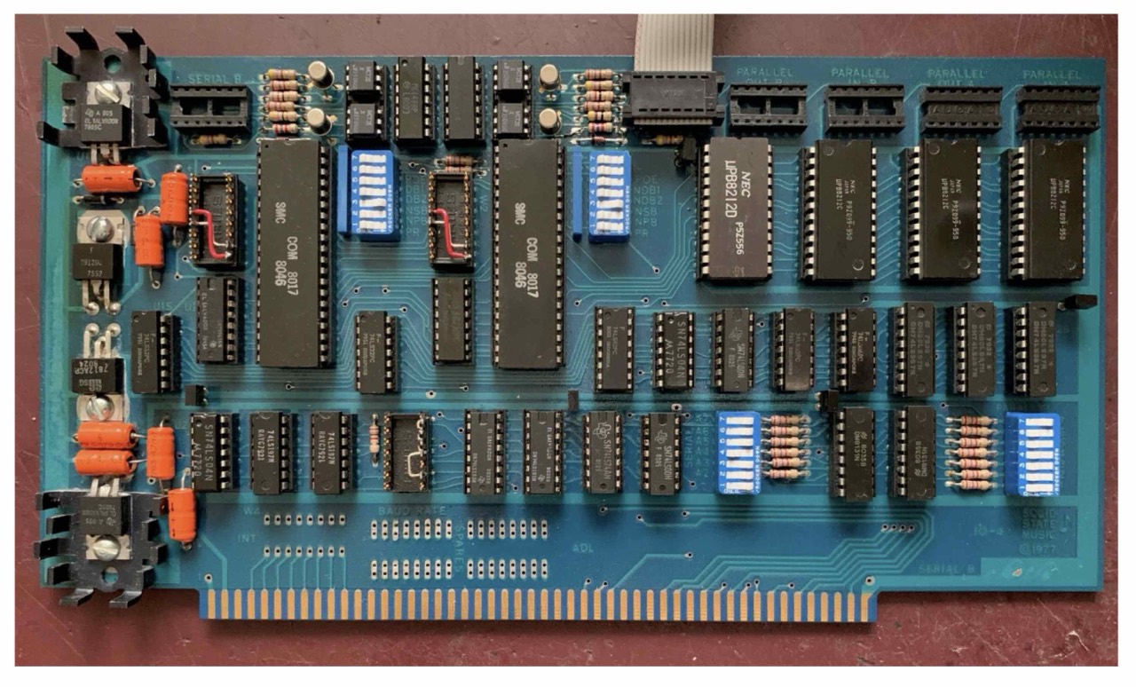
I know of three variants of the IO-4, one with the silver (exposed) conductor tracks (V1), one with a coating (V2) and a third
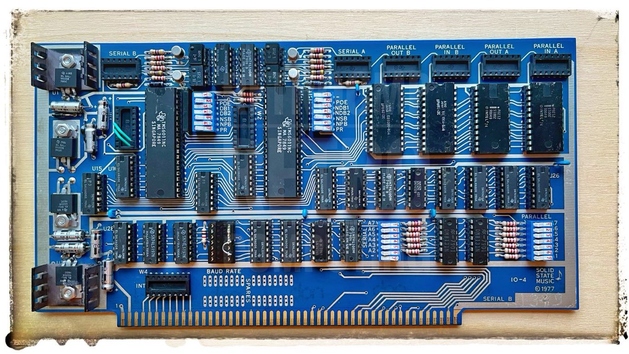
I have two cards of type 100-0062, but these are listed under the ICC (international cybernatics corporation) brand. Others appear under the names Gould and Modicon, but otherwise look identical.
The ICC 100-0062 is almost identical to the IO4 (please read here). The IO4 user's manual can be used for the settings.
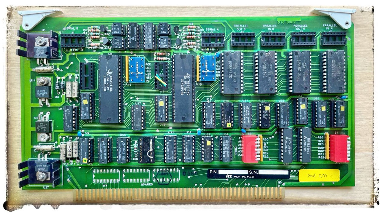
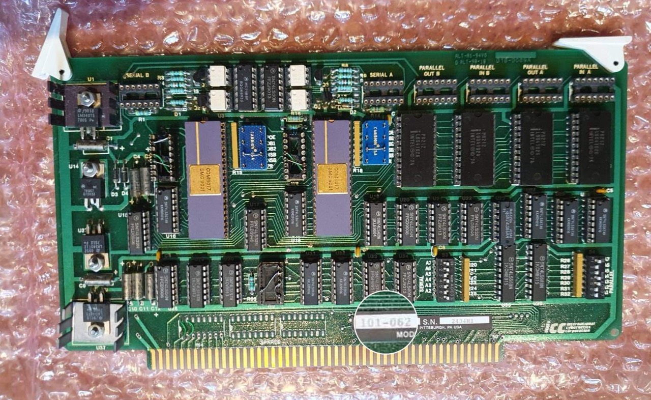
There is another variant, the ICC Modicon 101-062. But it seems to me that both are identical.
I/O Console Connection
To be able to work with the IO4 at all, you must first establish a connection between J1 and/or J2 (Serial A/B) and the serial DB25 connector. In other words, the console connection. This is basically described in the manual on page 4-3, see the next illustration.
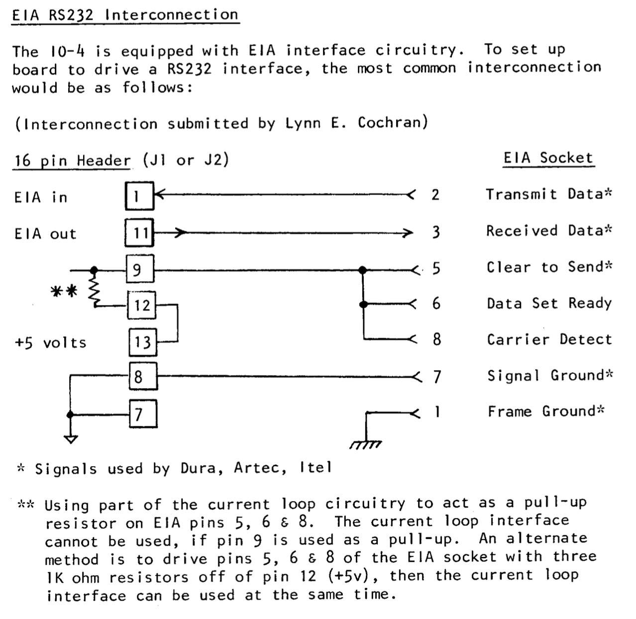
The following overview is from Mike Douglas.

Serial A/B      DB25
--------------------
1       RCV     2
7/8     GND     7
11      XMT     3
13/14   +5V     18
--------------------
And this is what it looks like when it's finished.
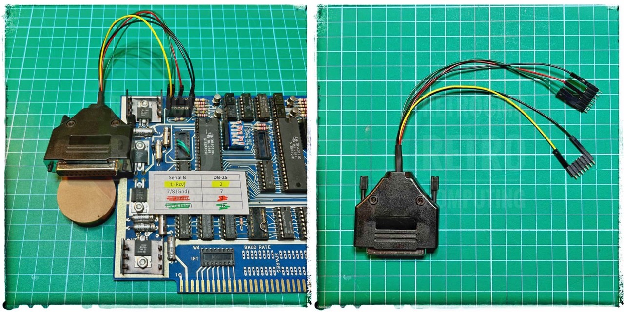
Once you have built/established this connection, most of the work is done. The rest is relatively easy. My connector cable is relatively primitive, but it can be used universally.
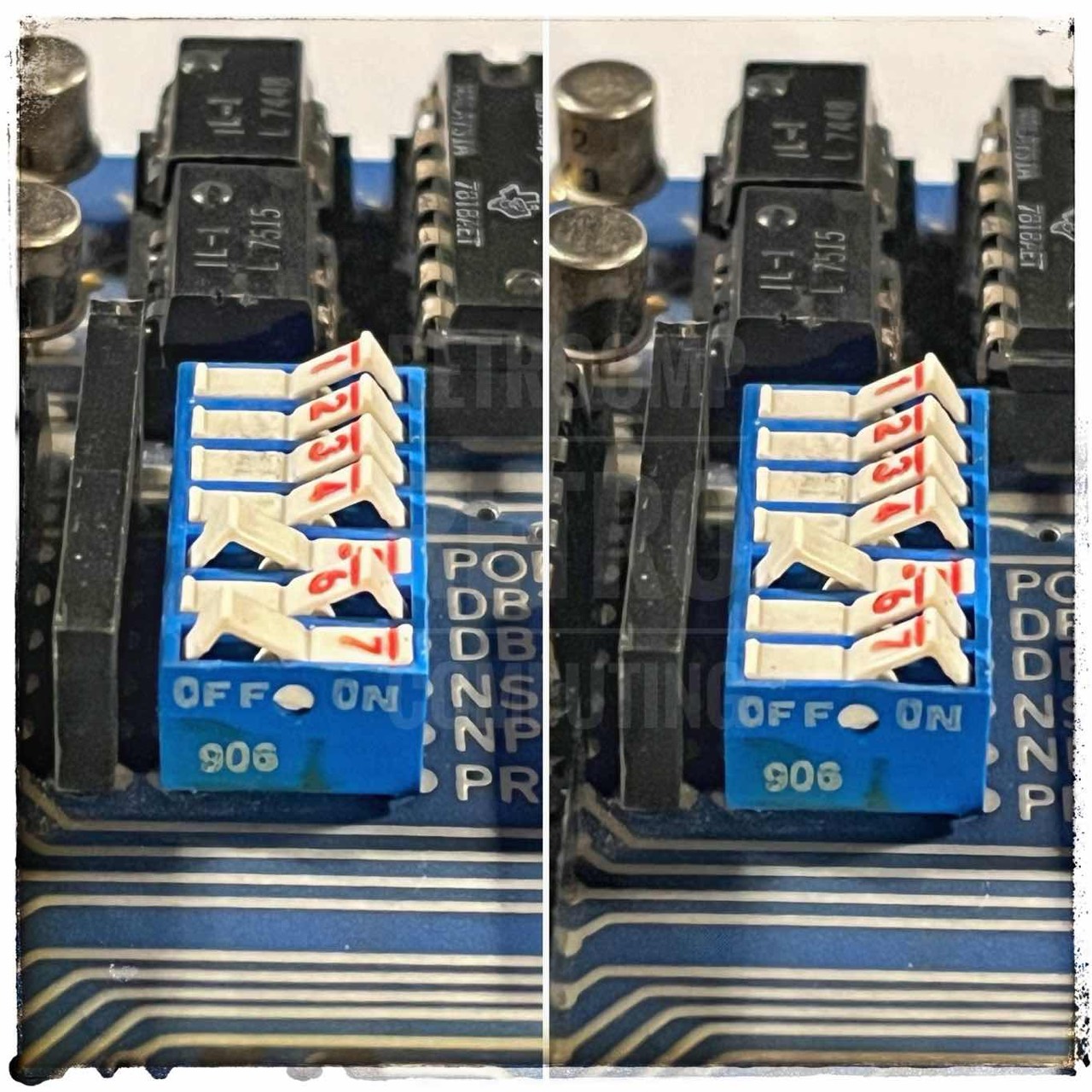
Settings and More
S1/S2 - CNTRL - UART
UART = Universal Asychronous Receiver Transmitter
see manual p. 3-1

ON = 1 or closed
OFF = 0 or open

(1) not used
(2) POE - parity odd or even
(3) DB1 - data bits S1
(4) DB2 - data bits S2
(5) NSB - stop bits
(6) NPB - parity bit
(7) PR  - port reversal

- IMSAI: 8N1, port reversal ON
- MITS : 8N1, port reversal OFF
S3 - SERIAL
A very important switch is S3, which is used to set the serial address. I use the IO4 in my IMSAI. Here, the console is on ports 2 and 3. Unfortunately, the address setting for IO4 is not as flexible as for the Interfacer 1. Here you can set the console port A to ports 2 & 3 and the transfer port to ports 4 & 5.
With IO4, you can only address a whole 4-port block, for example 0 to 3. As a result, you can only use serial B (console ports 2, 3) for the IMSAI. Ports 0 & 1 can not be used with the IMSAI. Too bad.
But the IO4 fits perfectly to the Altair 8800 as a direct replacement for the 88-2SIO. Console port A is at 10h & 11h and the transfer port B at 12h & 13h.
see manual p. 3-4

ON = 1 or closed
OFF = 0 or open

addresses   A7 A6 A5 A4 A3 A2
-----------------------------
0 to 3      1  1  1  1  1  1    IMSAI
4 to 7      1  1  1  1  1  0    2^2=4d=4h
...
10 to 13    1  1  1  0  1  1    MITS 2SIO, 2^4=16d=10h

serial A = 0,1 or 4,5 or 10,11 (status,data)
serial B = 2,3 or 6,7 or 12,13 (status,date)

- use port reversal (PR) to exchange status/data
- MITS -> (status,data)
- IMSAI -> (data,status)
W1 & W2 - STATUS
see manual p. 4-2ff

- IMSAI: 4-10, 5-9  (tested)
- MITS:  4-9,  5-10 (tested)
- MITS:  4-9,  5-16 (88-SIO, Rev. 1)
- MITS:  4-14, 5-10 (88-SIO, Rev. 0)

I use 4-9, 5-10 with the Altair FDC+ (Mike Douglas).
W3 - BAUD RATE
This is very simple. Just wire pins 11-12-13-14 to the desired baud rate. In most cases to pin 9 (9,600). Done!
Issues
LS or not LS
In the following drawing, I have marked several ICs with a red dot. Why? As mentioned above, I also have two ICC Glould boards (100-0062). But despite identical settings to IO4 they did not work (at first) on my test IMSAI. It took me a whole day to find the "error". Actually it was not a bug at all.
In the drawing you will find the exact designation of the individual TTLs. Some are Low Power Shottky, some are not and some have the LS in ( ). And this is exactly where the problem was for me. In my IMSAI test system, the TTLs marked in red must not be LS ICs. Problem solved. Why? I don't have the technical knowledge. Just because this is the case for me doesn't mean it has to be the same for you. I know from Mike Douglas that he had no problems.
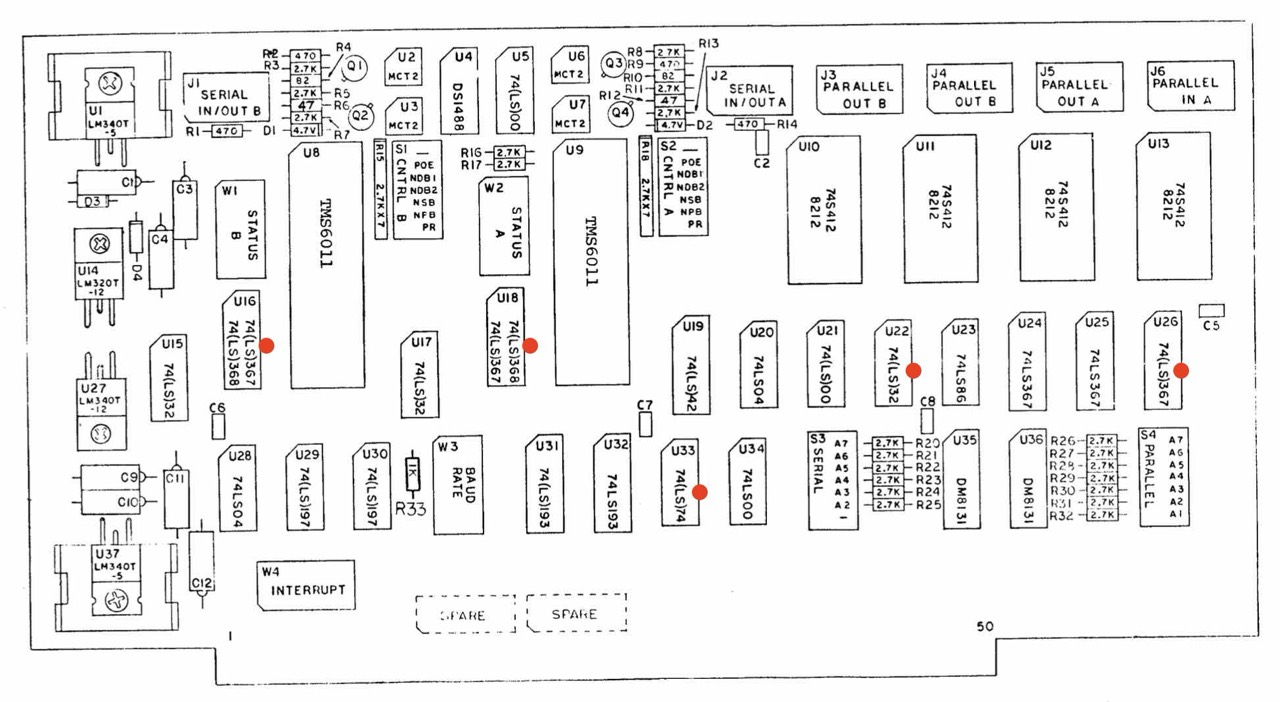
Update 03/23/2024: I think I've circled the problem further. It is most likely due to the 74367 TTLs and in particular U25 and U26, where I need 74367. U16, U18 and U24 work with 74LS367. If you want to be on the safe side, simply replace the LS TTLs. Of course, the power consumption will then increase slightly.
Short note on compatibility: LS74367 = N8T97 = DM8097 = MC6887.
Circuit Board Check
To avoid short circuits, the following check is always recommended in the old S-100 board building instructions. Actually, it is mandatory.
Check every unkown board to ensure that the +8, +16, -16 volt buses are not shorted to one another or to ground (GND). Using an ohmmeter (multimeter), make the following measurements. You should measure no continuity (no beep) in any of these measurements.
Negative voltages (7905) are of course only needed by a few S-100 cards but these are the most dangerous ones.
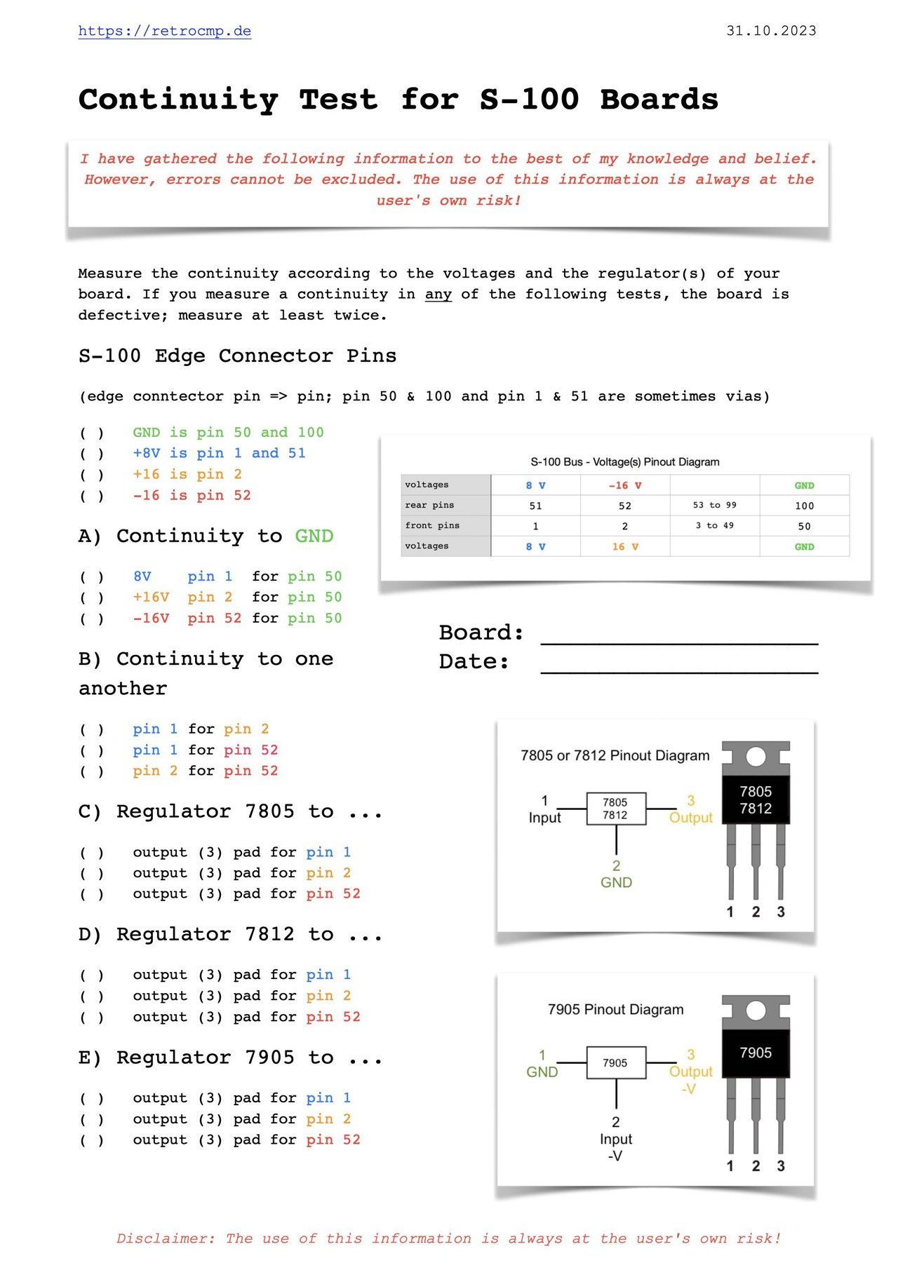
These simple tests take a maximum of five minutes, but can save you several hours of work!
Internal Links
External Links
- S100 Computers: Solid State Musik IO-4
- Wikipedia: Gould Electronics