<-- Back to Part 4: Emulator
--> Go to Part 6: The High Nibble
Power Supply Unit
Last revision of this page: January 26, 2025

- General
- Series (0)
- Series (1)
- Series (I)
- Series (F)
- Transformer
- Tranex 4-3751 (PS-28C & D)
- Tranex 4-3819 (PS-28C-U)
- Links
- References
General
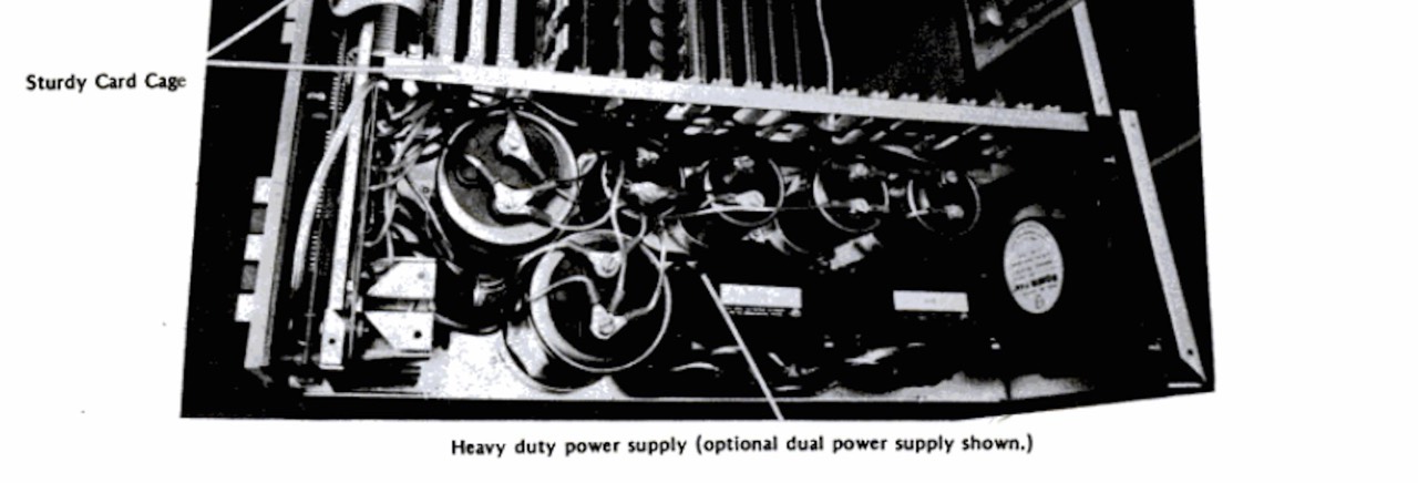
[Thomas Fischer] The first IMSAI's used a 10 amp power transformer [Signal 8063-A], the PS-A choke/filter board, and rectifier/heatsink assembly (mounted to the rear of the front sub-panel). Two large electrolytic "can-style" capacitors were held to the base plate with circular clamps and connected to the rectifiers with ring terminals at the top screws. Connected in parallel, they provided filtering for the unregulated 8 volt DC supply, while two smaller axial lead electrolytics mounted on the PS-A board filtered the unregulated plus and minus 18 volt supplies. I estimate between 100 and 200 of these machines were shipped; a few languished in Engineering, Marketing, and Customer Service for a year or so before they were scrapped.
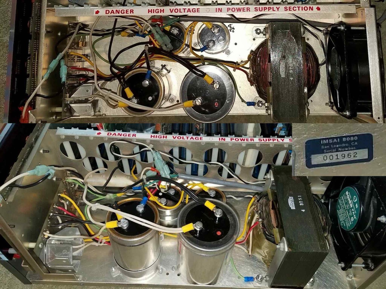
In early 1976, a new 28-amp power supply dubbed the PS-28 became standard issue, incorporating a TRANEX [4-3751] power transformer and 16 1/2" x 5 3/4" power supply board. This cumbersome arrangement included three line chokes, ceramic line filter caps, rectifier/heatsink assembly, two 80,000 mfd. and two 10,000 mfd. electrolytics that were now mounted to the PS-28 board with the screw terminals in contact with the board. A fuse clip arrangement provided for short-circuit protection. Sadly, the whole arrangement of line voltage layout was a dangerous design exposing the builder and user to potential shock in the area of the fuse clips, power switch, chokes and several other areas.
By June of 1976 the PS-28C U was introduced for the export market. It used a dual-primary winding on the transformer to allow the user to configure the supply for 110-120 volt, or 220-240 volt operation. In late 1982, FFC introduced a resonant circuit supply using a Zambre-designed transformer and non-polar capacitor. Although heavier than the PS-28 transformer, the new supply now produced over 30 amps on the unregulated 8 volt supply with inherent stability and self-regulating qualities. Only 100 of these improved supplies were shipped. [2]
The basic power supply unit was the PS-C 20 with up to 20 amperes at +8 volts and 3 amps each at +16 and -16 volts (unregulated), 115 or 110 volt 60 Hz input. This appears in the January 1976 price list.
Then there was a special Power Supply Module (PSM): "A special module which can be added to PS-20 to increase the 8 volt output to a maximum of 30 amps." This appears also in the January 1976 price list.
Then there was the PS-C 28 [my IMSAI] with 28 amps (on the 8V line). This appears about August 1976. In the November 1977 price list this PSU costs $100 more as kit and $179 in the assembled version.
And after the PS-C 28 there was the PS-28U. This is describes in the IMSAI manual by Fischer-Freytas, 2002. This uses a Tranex 4-3918-1 transformer. This transformer can be individually adjusted to different voltages. This was important for the European market.
According to Notice of Trustee's Sales there are six variations of the power supply boards: PS-C, PS-F, PS-G, PS-J, PS-K and PS-P.

Series (0)
According to Ross Milbourne and my researches there are four separate IMSAI serial number series. I refer to these as: (0) - (1) - (I) - (F)
I would like to take this opportunity to thank the Milbourne family for kindly providing me with a large number of pictures from the IMSAI collection of the late Ross Milbourne (Northumberland, United Kingdom). The following pictures are from his and my own collection.
001-001 --> 001-147
- No rectifier PCB at the front.
- Mounted directly on the base plate.
- Signal 8063-A transformer
- Capacitor connections at the top.
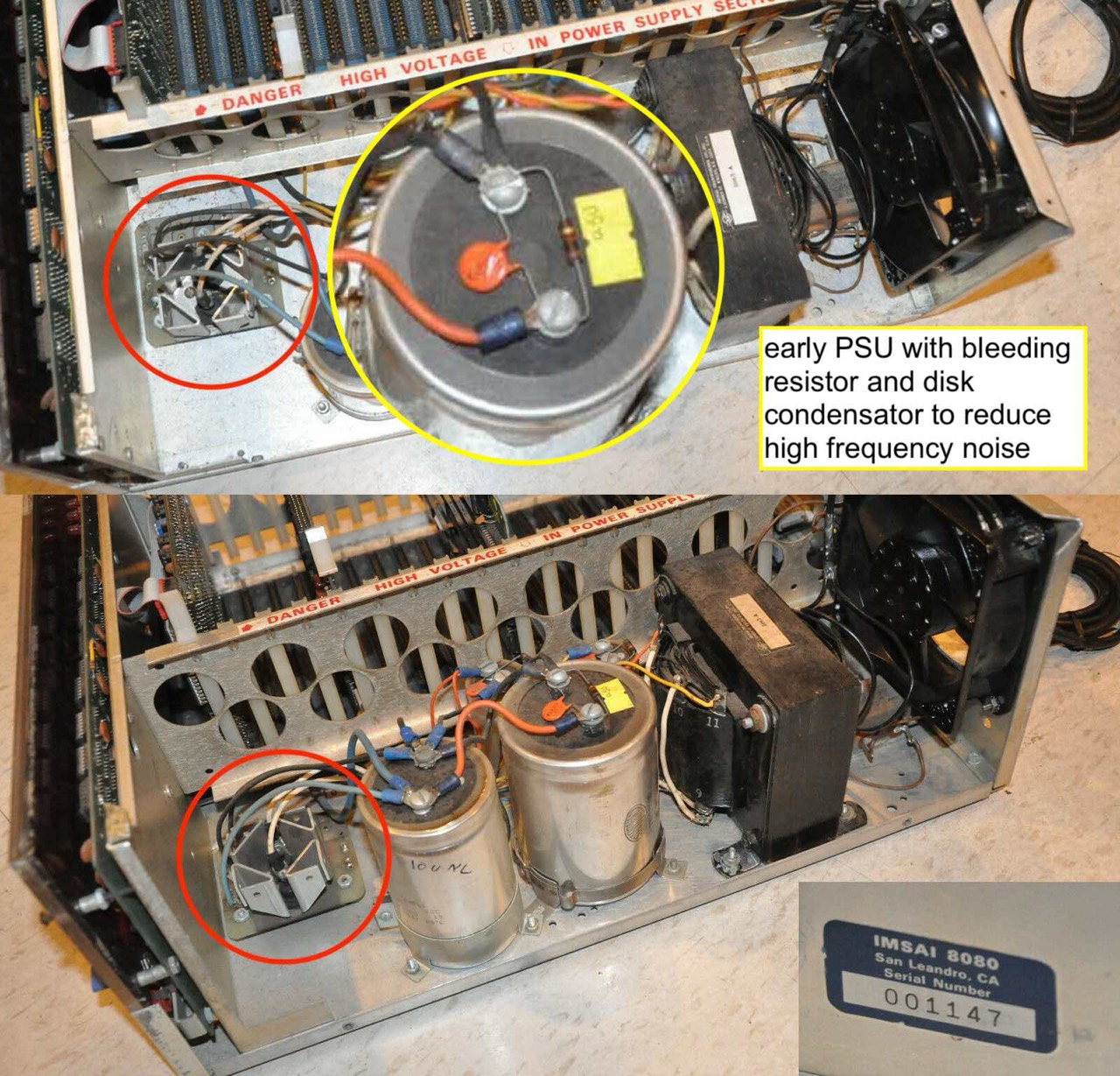
001-147
- Transformer: Signal, 8063-A, 10 amps [2]
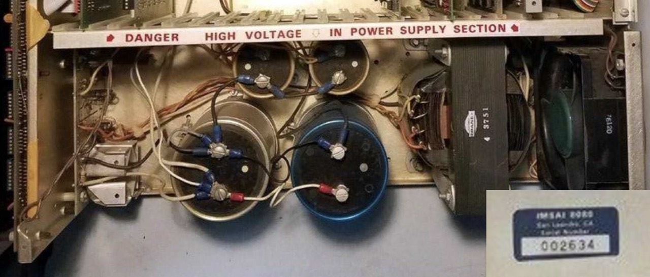
The following picture is interesting because the large capacitors have both an additional resistor and a disk capacitor. Why? The resistor is only used to bleed the capacitors when the current is switched off. Especially with the 18V capacitors, it can sometimes "spark" if you work on the capacitors too early. The S-100 cards can also be damaged if they are installed or removed too quickly! So, watch out. With the newer IMSAI PSUs and my N* Horizon, these resistors are already integrated on the respective PCBs.
Opinions seem to differ when it comes to capacitor, as I found out during my research. Some say that the capacitors do help, others say that they can amplify the high frequencies. As I am not an expert, I will not comment. The newer IMSAIs, those with the additional base plate by the power supply unit (from approx. #002-951), have three radio frequency interference suppression chokes fitted as standard.
001-258 --> 002-806
- With additional rectifier PCB at the front.
- Mounted directly on the base plate.
- Signal 8063-A, later TRANEX 4-3751 transformer
- Capacitor connections at the top.
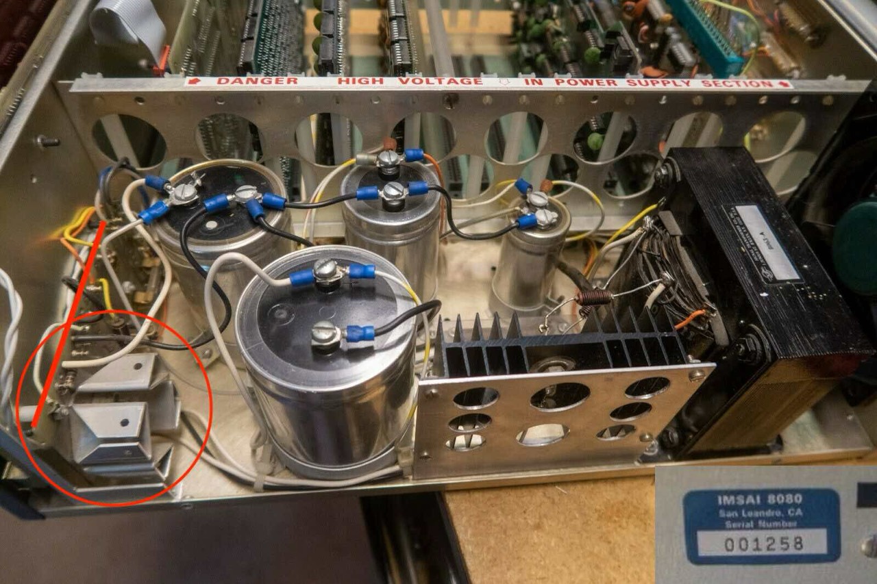
001-258
- Transformer: Signal, 8063-A, 10 amps [2]
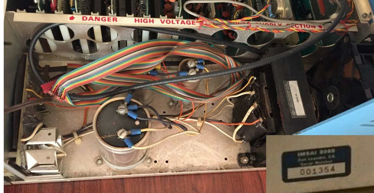
001-354
- Transformer: Signal, 8063-A, 10 amps [2]
001-378
- Transformer: ???

001-416
- Transformer: Signal, 8063-A, 10 amps [2]

001-458
- Transformer: ???

001-573
- Transformer: Tranex 4-3751, 28 amps [2]

001-962
- Transformer: Tranex 4-3751, 28 amps [2]
002-041
- Transformer: Tranex 4-3751, 28 amps [2]

002-577
- Transformer: Tranex 4-3751, 28 amps [2]

002-634
- Transformer: Tranex 4-3751, 28 amps [2]
002-751
- Transformer: Tranex 4-3751, 28 amps [2]

002-806
- Transformer: Tranex 4-3751, 28 amps [2]

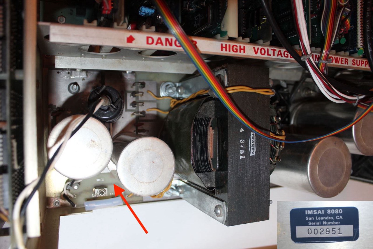
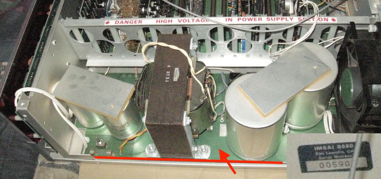
002-951 --> 005-90?
- No additional rectifier PCB at the front.
- Mounted on a secondary plate.
- TRANEX 4-3751 Transformer
- Capacitor connections at the bottom.
- Radio frequency interference suppression chokes
002-951
- Transformer: Tranex 4-3751, 28 amps [2]
005-90?
- Transformer: Tranex 4-3751, 28 amps [2]
Series (1)
According to Ross Milbourne and my researches there are four separate IMSAI serial number series. I refer to these as: (0) - (1) - (I) - (F)
- like the last ones in series (0)
- No additional rectifier PCB at the front.
- Mounted on a secondary plate.
- TRANEX 4-3751 Transformer
- Capacitor connections at the bottom.
- Radio frequency interference suppression chokes
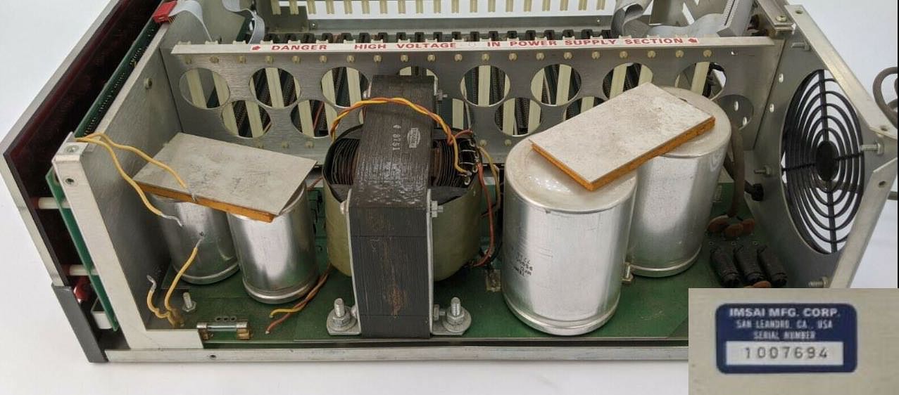
1-007-694
- Transformer: Tranex 4-3819, 28 amps, dual primary
Series (I) - (I)nternational
According to Ross Milbourne and my researches there are four separate IMSAI serial number series. I refer to these as: (0) - (1) - (I) - (F)
Basically, these IMSAIs belong to the series (1), only the transformer is different. Thomas Fisher: "By June of 1976 the PS-28C U was introduced for the export market. It used a dual-primary winding on the transformer to allow the user to configure the supply for 110-120 volt, or 220-240 volt operation." [2]
I-011-110
- Transformer: Tranex 4-3819, 28 amps, dual primary
- Radio frequency interference suppression chokes

Series (F) - (F)ischer-Freitas
According to Ross Milbourne and my researches there are four separate IMSAI serial number series. I refer to these as: (0) - (1) - (I) - (F). The addition (F) comes from me.
025-139 K
- Transformer: Tranex 4-3819, 28 amps, dual primary

Transformer
- PS-10?: Signal 8063-A, single primary [2]
- PS-20: [7]
- There was also a dual PSU version with two transformers! [7]
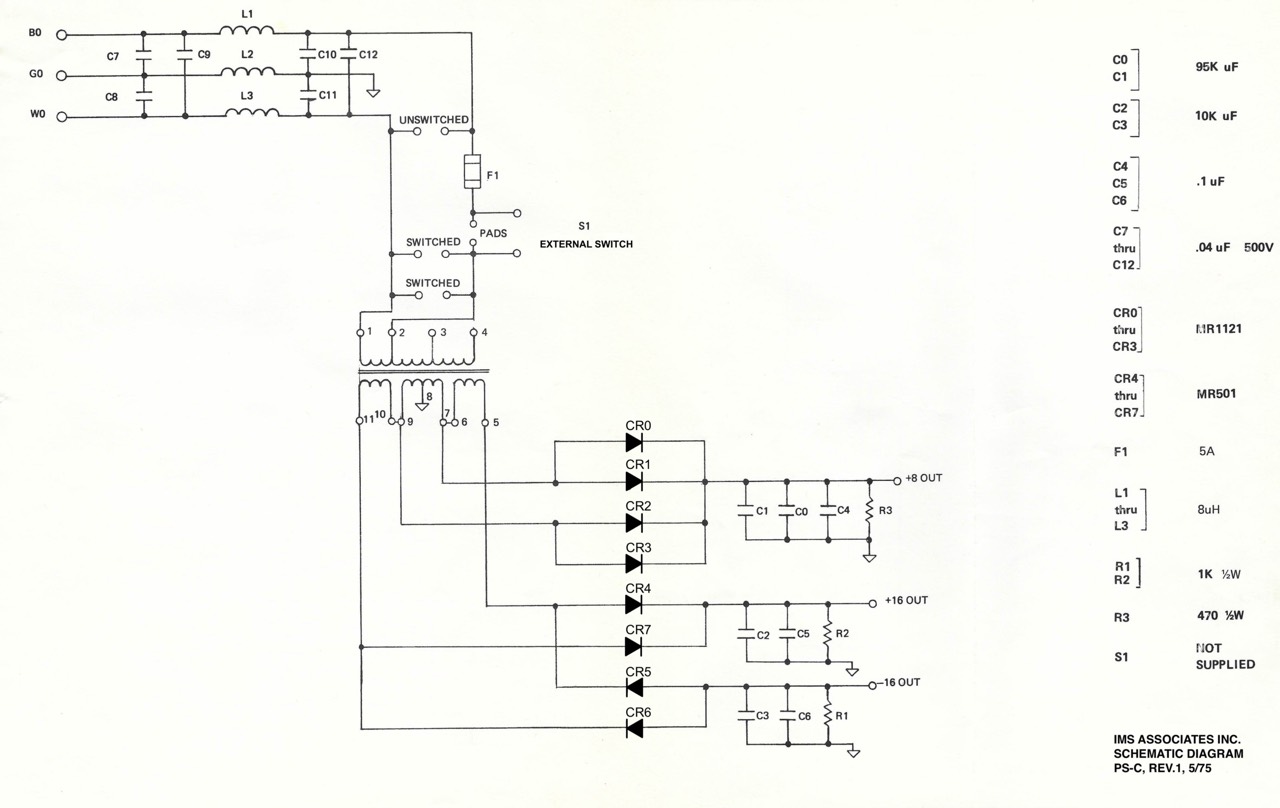
- PS-28C: Tranex 4-3751, single primary, original 5/76 [6]
- PS-28D: Tranex 4-3751, single primary, modified 1/77 [6]
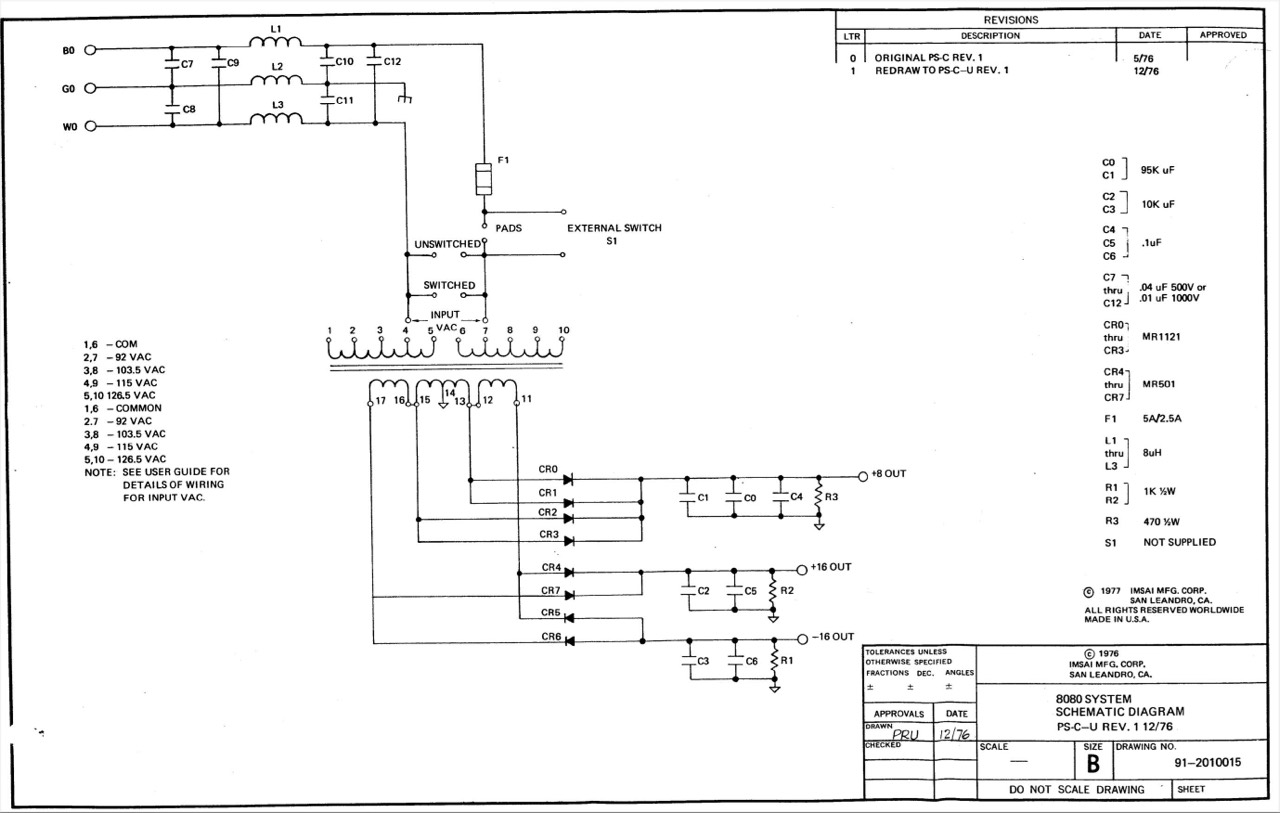
- PS-28C-U: Tranex 4-3819, dual primary [6]
Tranex 4-3751
The transformer primary is designed for a nominal 117 volt line, and 0, -10% and +10% taps for allow to adjustment for the line volatage variations.

Connect lug #1 with:
- -10%: 105 VAC
- +-0%: 117 VAC (*)
- +10%: 129 VAC

Restoration IMSAI (3): As with the rest of the power supply unit, the solderings here are also very sloppily made. I carefully removed all soldered connections, cleaned them and attached proper screw connections with screw locking varnish.
Basically this Tranex 4-3751 is working fine, even after sleeping 40 years.
Primary Side (IN)
Lugs: (#1), #2, #3, #4
According to the manual AC should be connected to lug (#1) and #2. In my case (*) AC was connected to (#1) and #3.
Secondary Side (OUT)
Lugs: #5, #6, #10, #11 and #7, #8, #9
Connect #7 to #6 and #9 to #10
Testting without load (output in VAC):
- #5: ... 13.5
- #7: ... 7.4
- #8: ... GND
- #9: ... 7.4
- #10: .. 13.5
Schematic
Tranex 4-3819
Schematic
External Links
- ...
References
- (↑) 01/19/1976 - Computerworld, page 43
- (↑) Thomas Fischer, https://web.archive.org/web/20180709082914/http://www.imsai.net/support/first_imsai.htm
- (↑) eBay sales pictures
- (↑) By courtesy of Rune Tapper, http://pc-museum.com/046-imsai8080/
- (↑) Don Caprio, http://s100chassis.pbworks.com/w/page/148514070/S-100%20Computer%20Chassis
- (↑) IMSAI User's Manual
- (↑) The Complete Microcomputer System, Jan 1976
My Series About the IMSAI 8080
--> Go to Part 0: Information
--> Go to Part 1 : Restoration (1) - Restoration (2) - Restoration (3)
--> Go to Part 2 : History
--> Go to Part 3 : Front Panel
--> Go to Part 4 : Emulator
--> Go to Part 5 : PSU
--> Go to Part 6 : The High Nibble
--> Go to Part 6 : RAM (of my North Star series)
--> Go to Part 7 : S-100 (of my North Star series)
--> Go to Part 8 : Capacitors (of my North Star series)