<-- Back to Part 2: History
--> Go to Part 3: Front Panel
Front Panel
Last revision of this page: January 25, 2025
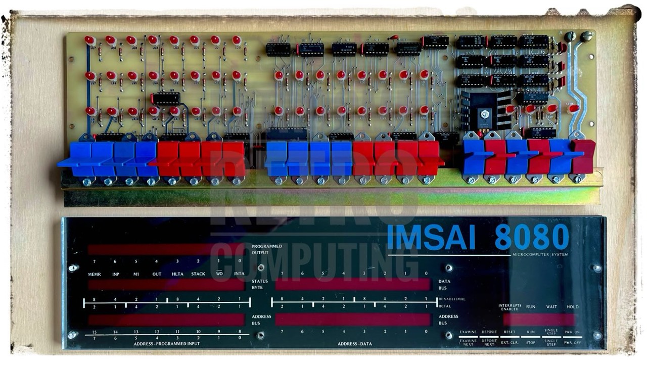
At first glance, the IMSAI 8080 front panel looks quite different from that of the Altair 8800; the colours alone. But if you take a closer look, you will see that the differences are not that big. How could it be otherwise, since both computers are almost compatible. The IMSAI is an improvement on the Altair.
Revisions
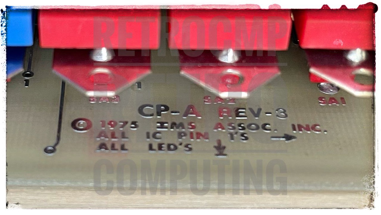
All information available to me from the internet always refers to revision 4 of the IMSAI front panel. However, my IMSAI with the serial number 005-293 has a front panel revision 3. At the moment (06/2023) I cannot say exactly where the differences are.
My IMSAI came with an original manual. The CPA scheme with revision 4 here has the date 02/27/1976. You remember, the first kits were sent mid of December 1975.
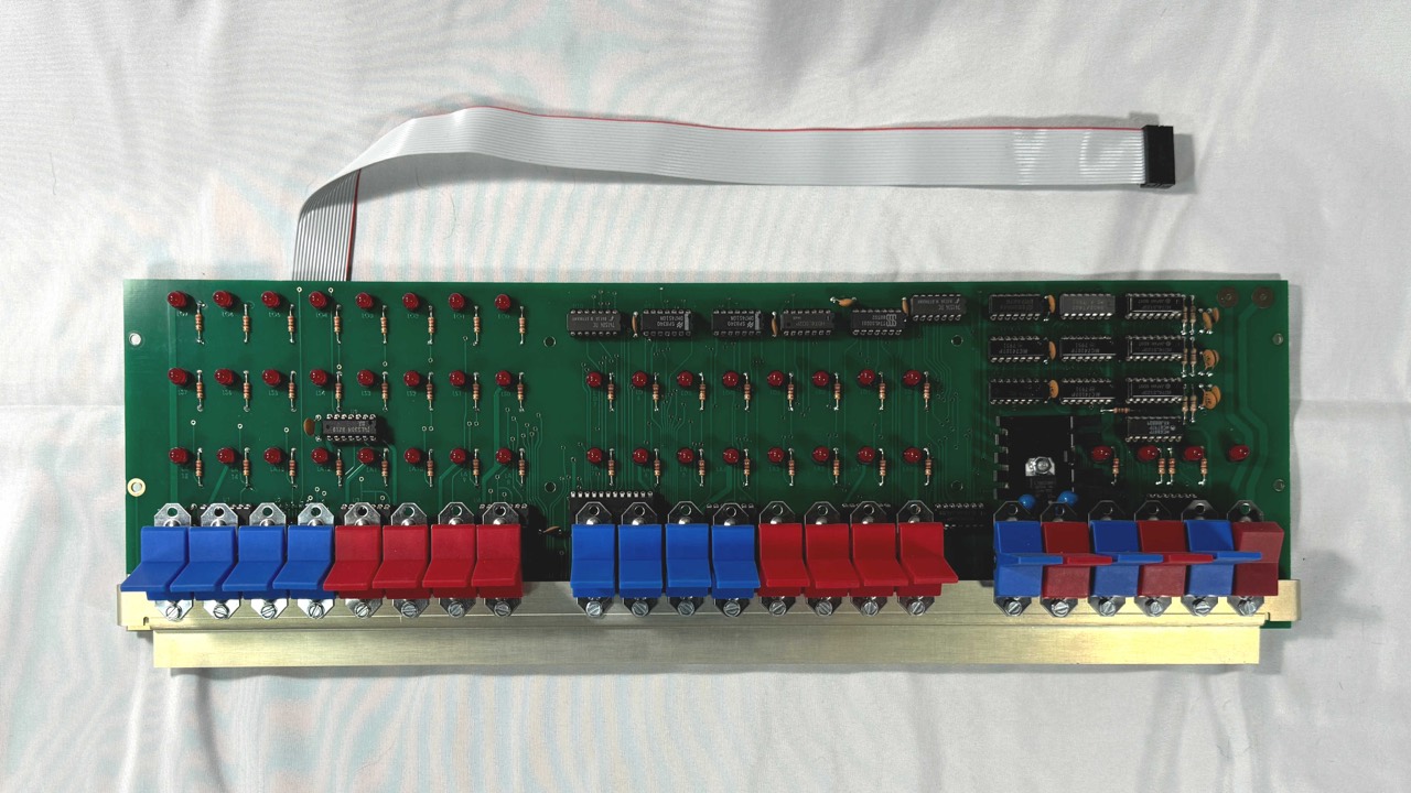
[Thomas Fischer] The CP-A Front Panel - Perhaps the most striking characteristic of the IMSAI is its front panel with "nibble-grouped" red and blue paddle switches and black masked LED's. Occasionally, an IMSAI 8080 will turn up with switch handles of a different color combination. IMSAI's early Marketing Development guru Bruce Van Natta had all-black switch handles on his in-house machine to signify his "unique-ness". Unusual and impractical, this choice of one color made the task of front panel switch programming less precise than when dealing with groups of four colors.
The first CPA boards were not solder masked until late spring of 1976. Like all IMSAI circuit boards, the CP-A was not provided with sockets, although they were an option. As mentioned above, low-profile Texas Instrument tin-plated contact sockets were provided. Many builders opted to use their own sockets, opting for gold-plated contacts or higher quality parts. High-profile sockets caused a clearance problem for the CP-A when the acrylic front mask set was installed.
The IMSAI was designed so that the CP-A was not necessary for system operation. This explains the choice of designer Joe Killian to put the data bus pull-up resistors on the MPU-A processor board and to use a 16 conductor flat cable with 16 pin "Dip" connector to connect the two boards together. This also allowed the CP-A to be used on a bus extender board (like the EXT) elsewhere in the motherboard for flexibility in testing and hardware debugging. It was not uncommon to find machines with multiple EXP motherboards, or an EXP-22 with address, data, and status lines cut to isolate the board. This was often done to allow use of two or more processors to operate in the same box, sometimes linked to each other's memory or I/O with flat cable(s). [1]
Basics
Before I assembled my Altair-Duino, I also always had an awkward feeling about operating it with the front panel. Then I watched the corresponding videos by Mike Douglas - The Altair Experience - and after that everything was actually easy. And now it's really fun.
Let's go. You can find the introduction to the basic operation at RetroComputerInstructionManual. And after that, you watch the said videos of Mike Douglas on the Altair.
Engineering Change Orders (ECO's)
Thomas Fischer made two papers with the ECO's. The 1st is from 2004 and the 2nd, a revised one, from 2008. Fundamental changes are concerning the ECO 76-0061.
According to Thomas Fischer [01] there were four ECO's:
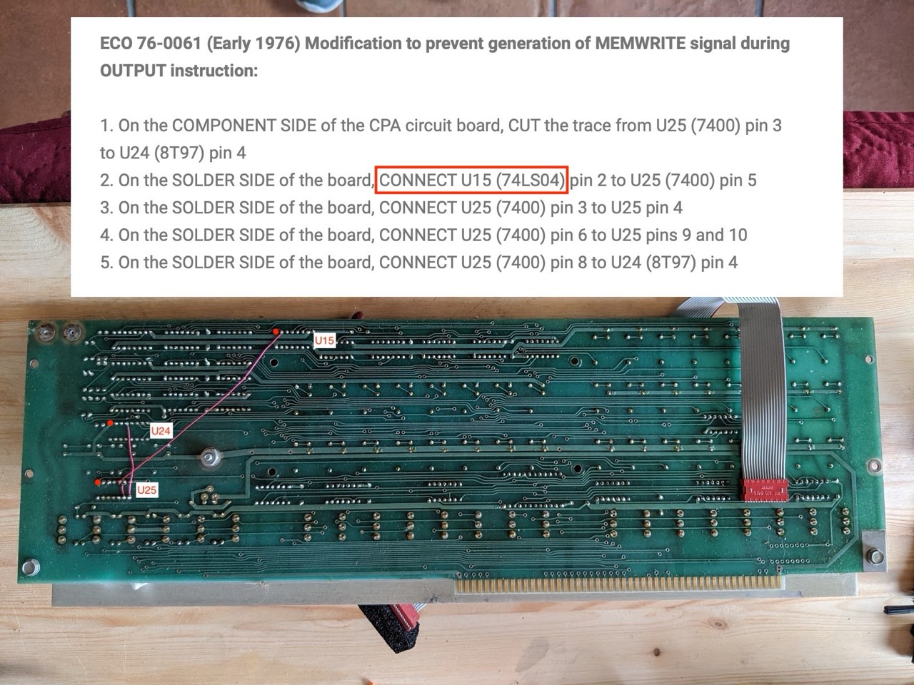
- ECO 76-0061 - This modification prevented generation of the MEMWRITE signal during the OUTPUT instruction
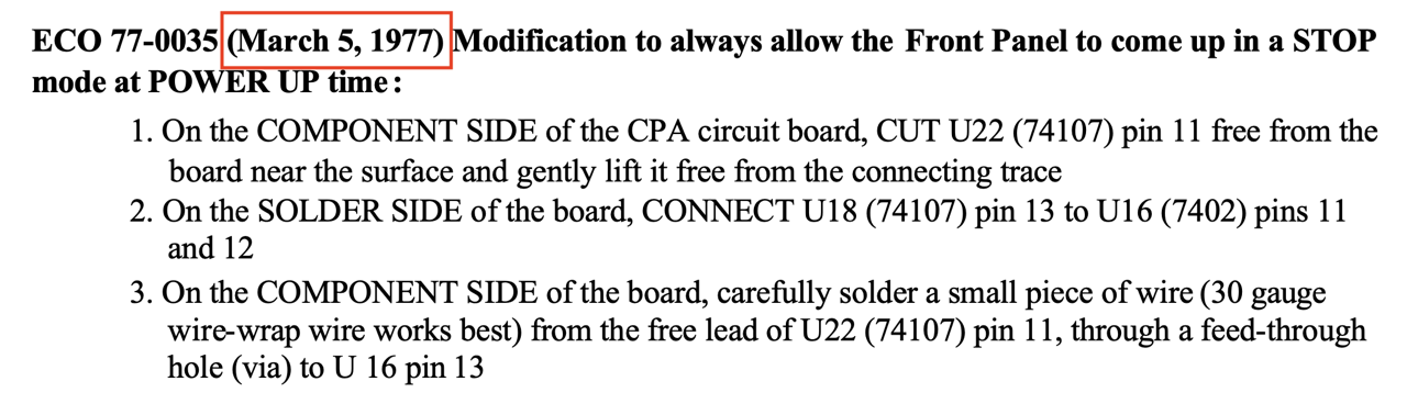
- ECO 77-0035 - This modification insured that the front panel always came up in the STOP mode on power up
- ECO 77-0039 - This modification made the RUN line agree with the bus definition, allowing use with IMSAI's dynamic RAM boards (RAM 16, RAM 32, RAM 64, RAM III)
- ECO 77-0098 - This modification prevented spurious triggering of the ONE-SHOTS during RUN mode, causing unpredictable program execution
ECO 76-0061
This modification prevented generation of the MEMWRITE signal during the OUTPUT instruction
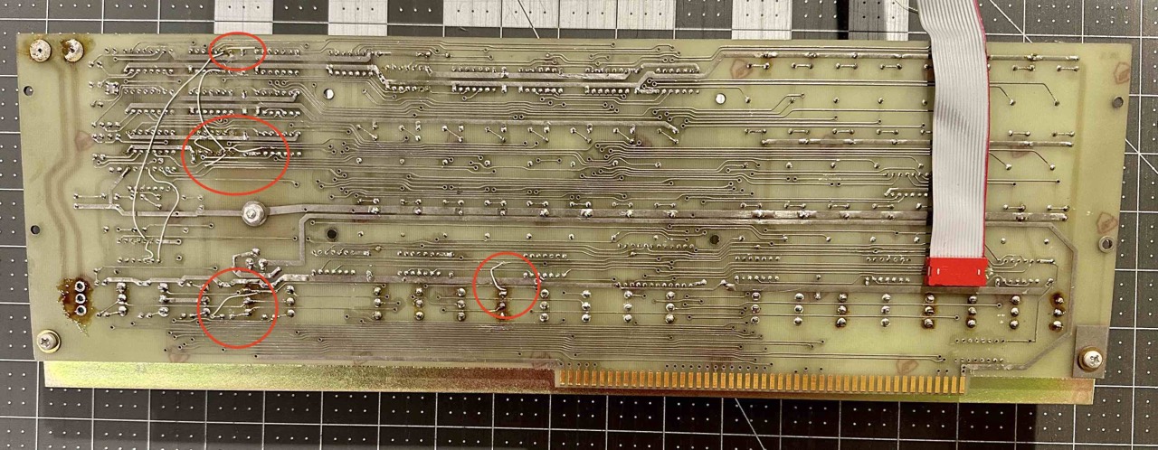
Variation with U16
On the back of my front panel the ECO 76-0061 with three additional wires can be seen on the left.
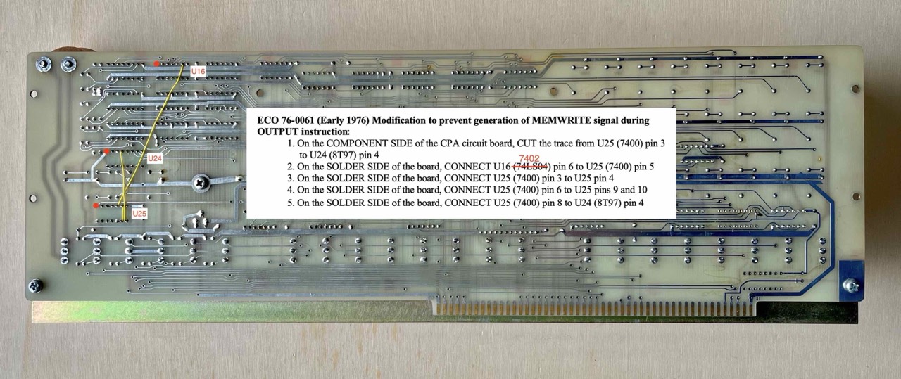
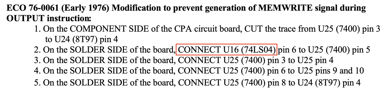
If you read this ECO carefully and look on the CPA (rev.4) at U16 you will notice that U16 is not 74LS04 but 7402! The manual also says U13 and U16 are 7402. Maybe a typo made by Fischer-Freytas Company.
Variation with U15
ECO 76-0061 (U16) and Others
ECO 77-0035
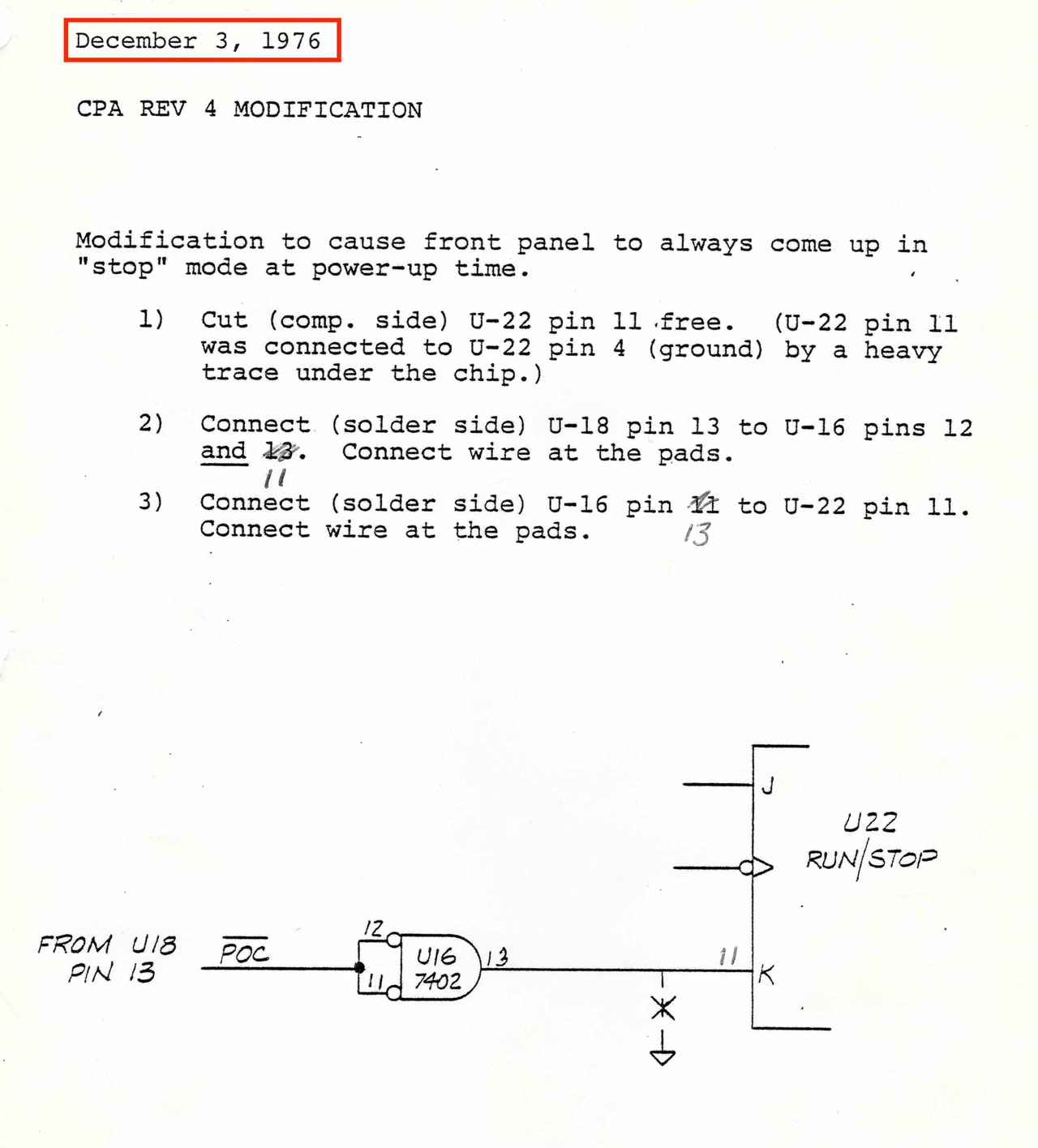
This modification insured that the front panel always came up in the STOP mode on power up
But, according to my original IMSAI manual this ECO came out earlier, latest in December 3, 1976.
Parastream
The founder and CEO of Parastream is Robert E. Weatherford, who worked at IMSAI from 1978 to 1979 (production test, engineering technician).
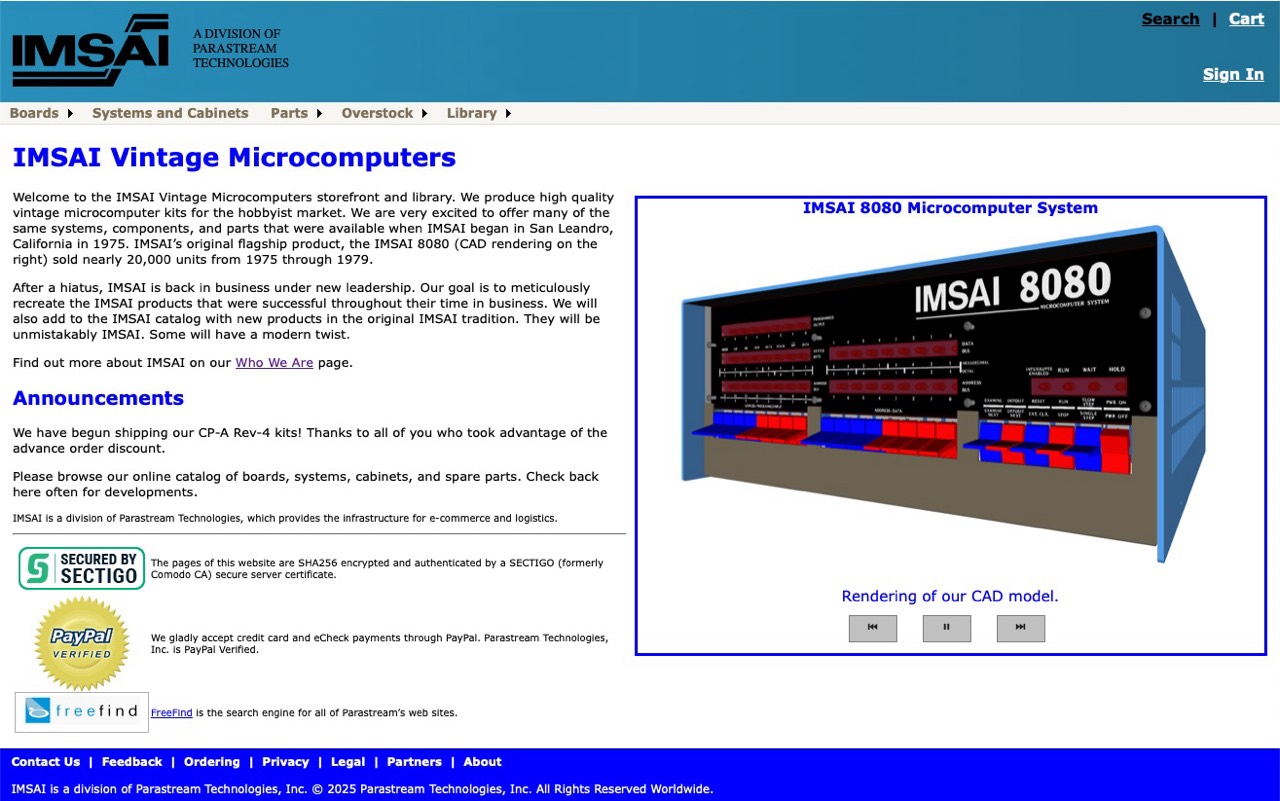
Welcome to the IMSAI Vintage Microcomputers storefront and library. We produce high quality vintage microcomputer kits for the hobbyist market. We are very excited to offer many of the same systems, components, and parts that were available when IMSAI began in San Leandro, California in 1975. IMSAI’s original flagship product, the IMSAI 8080 (CAD rendering on the right) sold nearly 20,000 units from 1975 through 1979.
After a hiatus, IMSAI is back in business under new leadership. Our goal is to meticulously recreate the IMSAI products that were successful throughout their time in business. We will also add to the IMSAI catalog with new products in the original IMSAI tradition. They will be unmistakably IMSAI. [5]
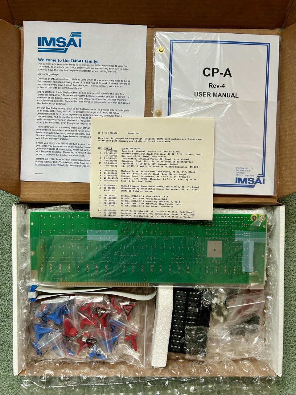
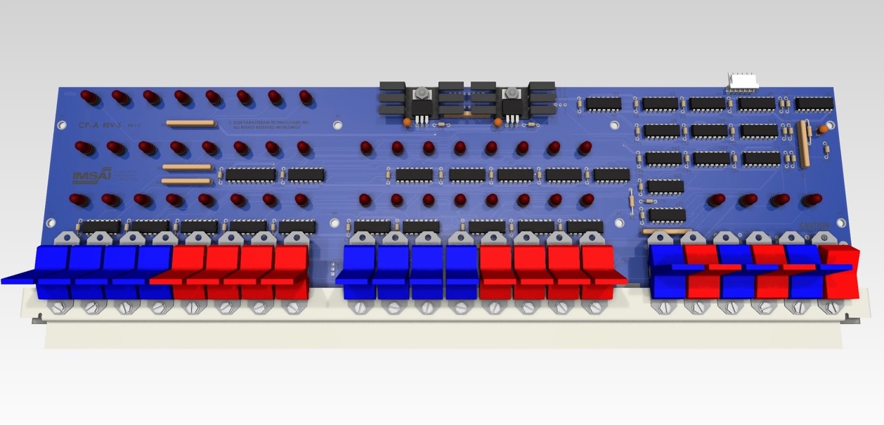
From everything I've read in the forums so far, the Parastream front panel is supposed to be great. The contents of the package and the documentation in particular look perfect.
External Links
- The basics: RetroComputerInstructionManual in HTML and PDF.
- Videos by Michael Douglas: The Altair Experience
- Videos by Shadow Tron Blog: IMSAI 8080 front panel replica and Emulator kit from the High Nibble - Videos 13, 13.5 and 17. The rest is of course also very interesting.
References
- (↑) Thomas Fischer, https://web.archive.org/web/20180709082914/http://www.imsai.net/support/first_imsai.htm
- (↑) https://imsaicomputers.blogspot.com/2020/01/imsai-8080-restoration-for-centre-for.html
- (↑) Thomas Fischer, IMSAI Board History: CPA Programmers Front Panel rev.4 Engineering Change Orders (ECO's), 7-23-2004
- (↑) IMSAI Manual, 1976
- (↑) Parastream, https://www.parastream.com/imsai/
My Series About the IMSAI 8080
--> Go to Part 0: Information
--> Go to Part 1 : Restoration (1) - Restoration (2) - Restoration (3)
--> Go to Part 2 : History
--> Go to Part 3 : Front Panel
--> Go to Part 4 : Emulator
--> Go to Part 5 : PSU
--> Go to Part 6 : The High Nibble
--> Go to Part 6 : RAM (of my North Star series)
--> Go to Part 7 : S-100 (of my North Star series)
--> Go to Part 8 : Capacitors (of my North Star series)